Method for filling a muffler cavity

a technology for filling and mufflers, applied in the direction of machines/engines, manufacturing tools, other domestic articles, etc., can solve the problems of fiber trapping and adverse effect on the joint quality of the muffler shell components

Inactive Publication Date: 2011-07-12
OCV INTELLECTUAL CAPITAL LLC
View PDF13 Cites 30 Cited by
  • Summary
  • Abstract
  • Description
  • Claims
  • Application Information

AI Technical Summary

Problems solved by technology

The trapped fibers subsequently have an adverse effect on the quality of the Joint between the muffler shell components.

Method used


Image

  • Method for filling a muffler cavity
  • Method for filling a muffler cavity
  • Method for filling a muffler cavity

Examples


Embodiment Construction

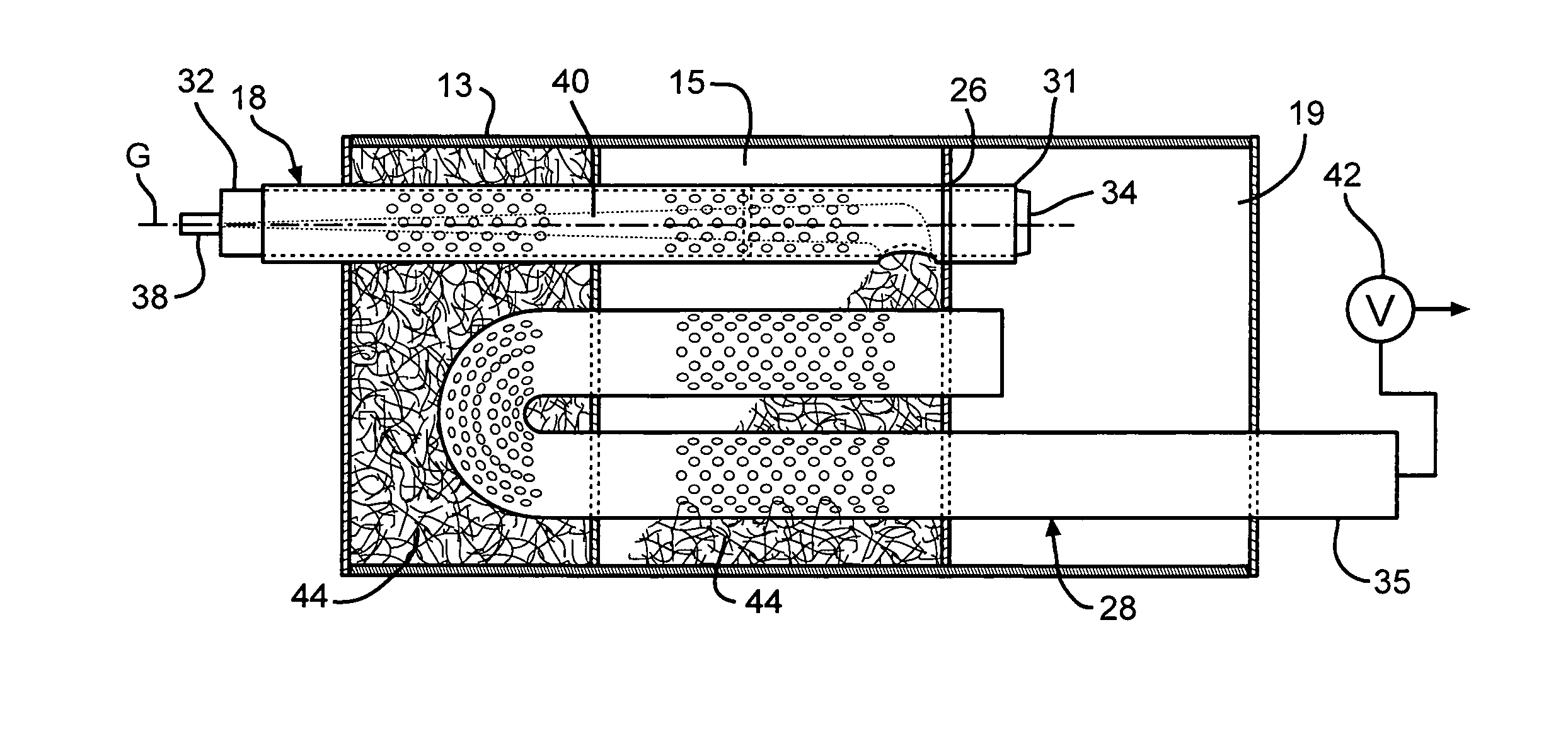
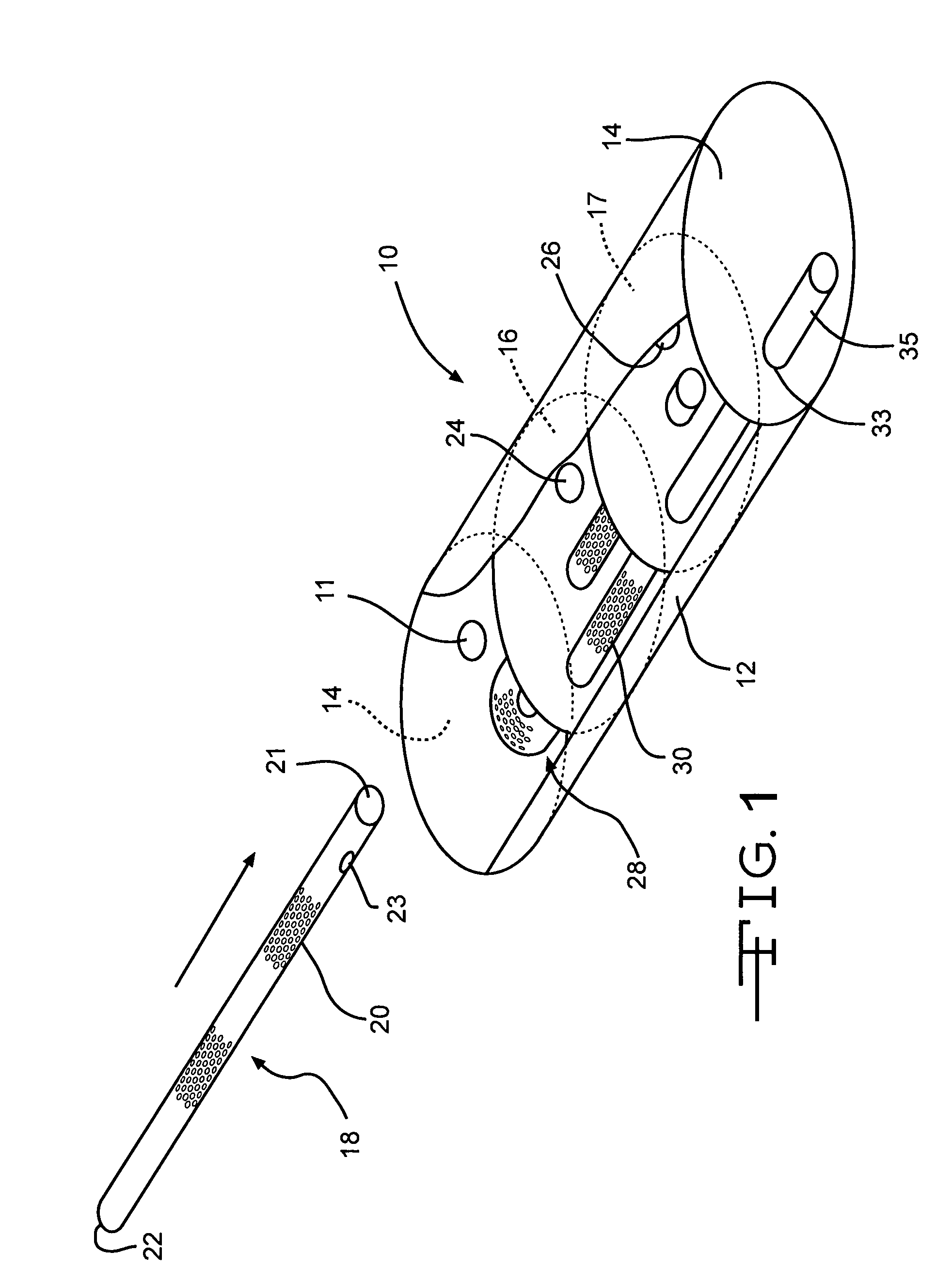
[0013]Referring now to the drawings, there is illustrated in FIG. 1 a common configuration for a muffler assembly. The muffler assembly, indicated generally at 10, is comprised of a main body portion 12 and end caps 14. Generally, the body portion 12 and the end caps 14 are formed from a metal or metal alloy material, although it will be appreciated that any suitable material may be used for the body portion 12 and end caps 14. The body portion 12 and end caps 14 can be formed using any suitable forming process, such as forming about a mandrel for the body portion 12 or stamping for the end caps 14, and can be formed having any suitable shape and dimensions. The body portion 12 and the end caps 14 are generally formed such that the completed muffler assembly 10 has an elongated elliptical shape, with the main body portion 12 being joined with the end caps 14 using any suitable method, such as welding or crimping. It will also be appreciated that other shapes and configurations can a...


PUM

PropertyMeasurementUnit
diameteraaaaaaaaaa
diametersaaaaaaaaaa
outer diameteraaaaaaaaaa

Abstract

A method for filling a muffler with a fibrous material is disclosed. The muffler includes partitions which form a first chamber and second chamber, and a first muffler pipe having an outlet end. A filling aperture at one end of the second muffler pipe is positioned in the first muffler chamber. The second muffler pipe has a filling sleeve therein, the filling sleeve having a filling discharge opening that coordinates with the filling aperture of the second muffler pipe. The first muffler chamber is filled with fibrous material by applying a vacuum source to the first muffler pipe, which draws the fibrous material through the filling aperture. The filling aperture of the second muffler pipe is then positioned into the second muffler chamber, and the second muffler chamber is filled in the same manner as the first muffler chamber. The filling sleeve is then removed from the second muffler pipe.

Description

TECHNICAL FIELD[0001]This invention relates to a method of filling a muffler cavity with fibrous material. More particularly, the invention pertains to an improved method for filling a muffler cavity in a preassembled muffler shell with fibrous material.BACKGROUND OF THE INVENTION[0002]Exhaust mufflers often include a sound absorbing material within the interior of the muffler to absorb and attenuate the sound made by the escaping gases that pass through the muffler. Many types of exhaust mufflers are produced by mechanically joining multiple pieces to form a muffler shell. For example, one common type of exhaust muffler is known as a spun muffler. Spun mufflers are made by forming a sheet of material into the desired shape to form the muffler body and attaching end caps to this body by welding or crimping to form the muffler shell. Another common type of exhaust muffler is a clamshell muffler, which is assembled by joining an upper section to a lower section by welding or crimping....

Claims


Application Information

Patent Timeline
Patent Type & Authority Patents(United States)
IPC IPC(8): F01N1/24
CPCF01N1/04F01N1/24F01N13/18F01N2310/02F01N2450/06B23P2700/50Y10T29/49398Y10T29/49993Y10T29/49879
Inventor BRANDT, LUC J. L.CHARLIER, LEON
Owner OCV INTELLECTUAL CAPITAL LLC
Why Eureka
Try Eureka