
Chain ring power sensor for a bicycle

Active Publication Date: 2011-07-12
SRAM CORPORATION
View PDF23 Cites 41 Cited by
  • Summary
  • Abstract
  • Description
  • Claims
  • Application Information

AI Technical Summary

Benefits of technology

[0007]A chain ring based power meter is proposed that measures the amount of work done by a cyclist to propel a bicycle. The power meter includes an adapter ring that carries a series of spaced strain sensing elements. The adapter ring is designed to interface with the existing components of a crank set. In this regard, the adapter ring can be an add-on component to an existing crank set and thus does not require existing components of the crank set to be replaced or discarded. Additionally, it is believed the adapter ring can be installed relatively easily.

Problems solved by technology

One of the drawbacks of conventional power measuring systems, especially those that measure torque and angular velocity in a driven component, has been the difficulty in incorporating such a system into a bicycle.
Recreational cyclists, however, generally lack the tools and skill set to properly make such a modification.
A recreational cyclist, on the other hand, may object to the cost associated with replacing the crank set or the rear hub.

Method used


Image

  • Chain ring power sensor for a bicycle
  • Chain ring power sensor for a bicycle
  • Chain ring power sensor for a bicycle

Examples


Embodiment Construction

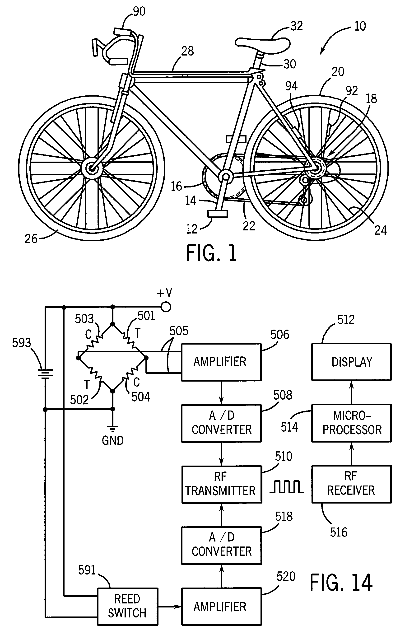
[0031]Referring now to FIG. 1, a bicycle 10 typically includes a pair of pedals 12 connected by a crank arm 14 to a chain ring 16. The chain ring 16 is coupled to the hub assembly 18 of the rear wheel 20 by a chain 22. The bicycle 10 is powered by a cyclist providing rotational forces to the chain ring 16 via the pedals 12 and crank arm 14. The rotation of the chain ring 16 is transferred by the chain 22 to the rear wheel hub assembly 18, which carries the rear wheel 20 into rotation via spokes 24 to drive the bicycle into motion. As is known in the art, the bicycle 10 also includes a front wheel 26 connected to the rear wheel 20 by a frame 28 that includes a seat post 30 and seat 32 for supporting a rider.

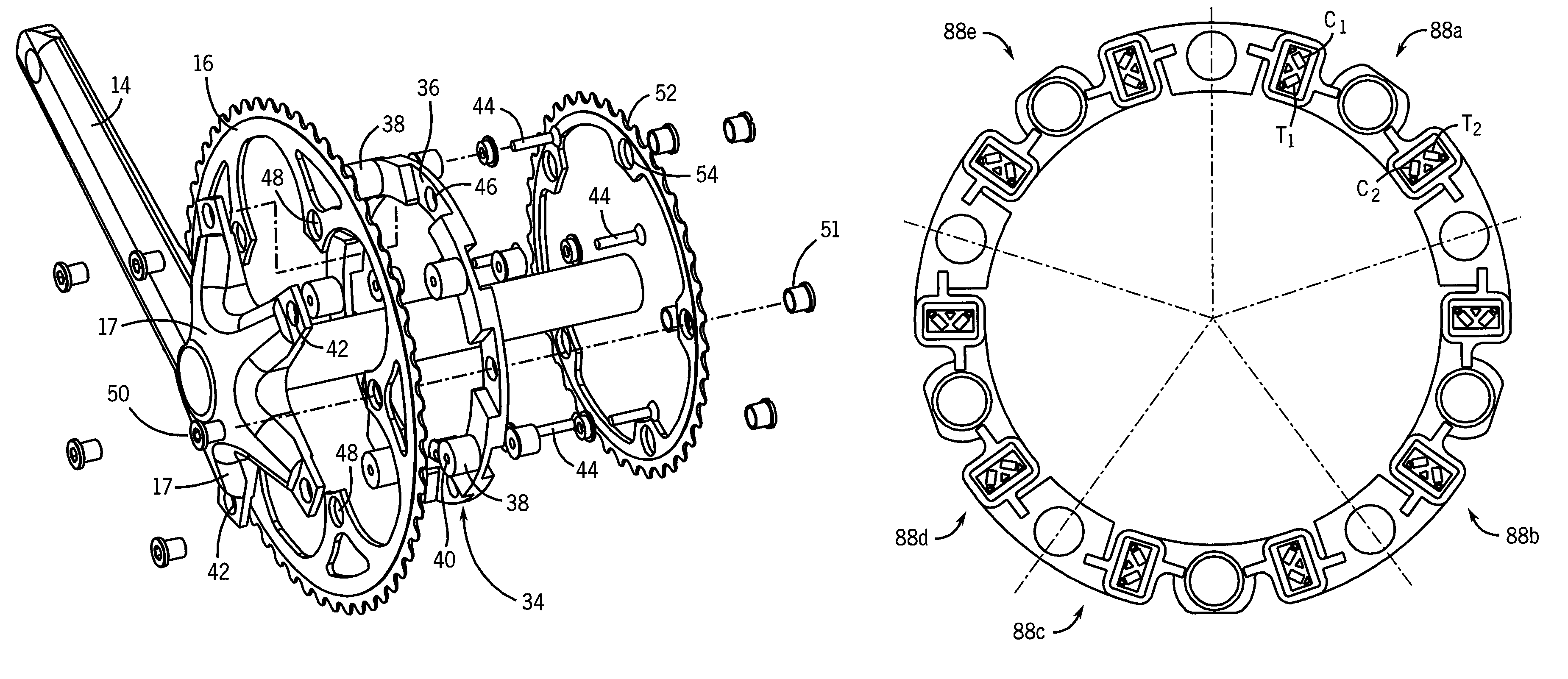
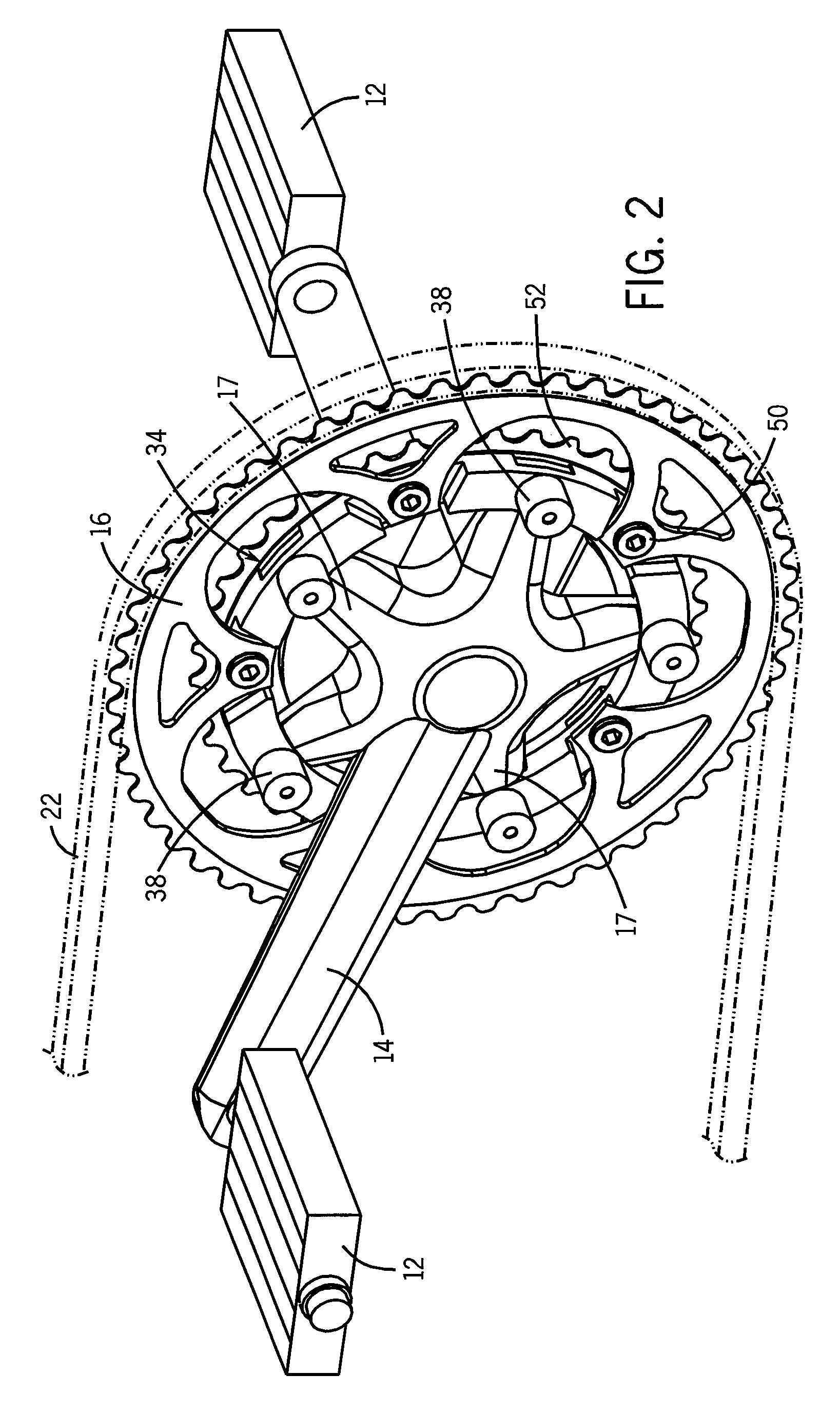
[0032]Referring now to FIGS. 2-4, in a conventional bicycle the chain ring 16 is mounted directly to the inner end of the crank arm 14, which is commonly referred to as the “spider” of the crank arm 14, and which defines a series of outwardly extending arms 17. The illustrated cra...


PUM


Abstract

A torque sensing arrangement has a set of strain sensors, such as strain gauges, mounted to an adapter that can be mounted to a chain ring of the crank set of a bicycle wheel. The adapter may have an annular body that can be used to retrofit the original crank set of a bicycle to have torque sensing components without having to replace the chain rings or the crank arm of the crank set. Together with angular velocity measurements, the measurements of the strain sensors may be used to calculate the amount of work or power exerted by the cyclist to propel the bicycle.

Description

CROSS-REFERENCE TO RELATED APPLICATION[0001]The present invention claims the benefit of U.S. Ser. No. 61 / 032,764, filed Feb. 29, 2008, the entire disclosure of which is incorporated herein by reference.BACKGROUND OF THE INVENTION[0002]The present invention relates generally to performance measuring systems for use with bicycles and, more particularly, to a chain ring based power measuring apparatus that measures the amount of work done by a cyclist to rotate a wheel of a bicycle.[0003]Power is generally defined as the product of torque and angular velocity or the product of force and velocity. In this regard, power cannot be determined directly, but can be calculated from torque and velocity information acquired as the cyclist propels the bicycle. As power corresponds to work done, cyclists are increasingly outfitting their bicycles with power measuring systems that provide speed and power feedback, such as instantaneous speed, instantaneous power, average speed, average power, and ...

Claims


Application Information

Patent Timeline
IPC IPC(8): G01L3/02G01L1/22
CPCG01L3/1457B62M9/105B62M6/50B62J45/411B62J45/421
Inventor AMBROSINA, JESSEQUINTUS-BOSZ, HARALDSHYDO, JR., ROBERT M.KOLDA, CLINT D.IVERSON, JEFFERY T.LOHR, JOSHUA G.
Owner SRAM CORPORATION
Features
  • Generate Ideas
  • Intellectual Property
  • Life Sciences
  • Materials
  • Tech Scout
  • Unparalleled Data Quality
  • Higher Quality Content
  • 60% Fewer Hallucinations
Learn More