Punching tool

a technology of punching tool and punching die, which is applied in the field of punching tools, can solve the problems of awkward change of punching tool and the inability of the punching tool to absorb large punching force, and achieve the effect of simple and rapid separation of the punching di

Active Publication Date: 2011-07-12
MATE PRECISION TOOLING
View PDF26 Cites 42 Cited by
  • Summary
  • Abstract
  • Description
  • Claims
  • Application Information

AI Technical Summary

Benefits of technology

[0004]The Object of the invention is based on creating a punching tool of the type described which provides secure locking by means of holding members against axial relative movements between the punching die and the die plunger, which permits a simple and rapid separation of the punching die from the die plunger, and wherein the large forces occurring in the course of the punching stroke are kept away from the holding members.
[0006]The novel punching tool initially offers the advantage that the strong loads during the punching stroke are transmitted via the front face of the die plunger, so that the holding members need not be correspondingly strong. The snap-in balls and their guide faces are only stressed by the considerably lesser forces during the return stroke of the punching die. The resilient ring also needs to exert only a minimal spring force on the snap-in balls in order to prevent the punching die from falling out of the bore in the die plunger outside of the guide bushing. Therefore the punching die can be easily separated from the die plunger or, vice versa, pushed into the bore in the front end of the die plunger and locked there. Regardless of the small or minimal spring force with which the resilient ring pushes the snap-in balls into the annular groove, the proposed locking against axial separation of the punching die from the die plunger is absolutely dependable as long as it is provided by means of a suitable selection of the diameters that the snap-in balls still engage the annular groove when the resilient ring rests against the bore wall of the guide bushing.
[0008]Also, in view of dependability of the locking, the resilient ring is usefully made of steel. It has furthermore been shown to be advantageous if the resilient ring is seated in an annular groove in the circumferential surface of the die plunger which crosses the center longitudinal axes of the transverse bores and is only slightly wider than the diameter of the resilient ring in axial section.
[0010]To assure axial freedom from play, in a useful embodiment of the invention the distance between the transverse plane in which the center longitudinal axes of the transverse bores are located, and the front end face of the die plunger, or of the bottom of the bore, is of such a size in relation to the distance between the central transverse plane through the annular grove and the back of the flange, or of the rear end face of the shaft of the punching die, that the punching die can be pressed axially against the die plunger by means of the spring-loaded snap-in balls.

Problems solved by technology

Since in this case the stressed surfaces are very small, the known punching tool cannot absorb large punching forces.
Moreover, changing of the punching tool is very awkward, since several screws must be removed and screwed back in again to accomplish this.

Method used


Image

  • Punching tool
  • Punching tool

Examples


Embodiment Construction

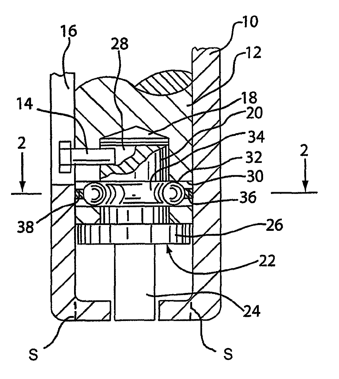
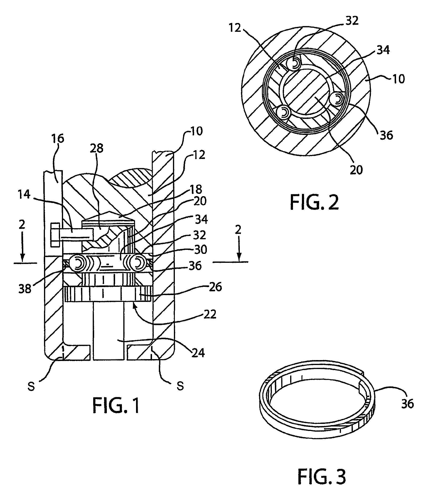
[0016]An exemplary embodiment of the invention will be explained in greater detail with reference to the accompanying figures. FIG. 1 shows a simplified longitudinal section through the front end of a guide bushing and of a die plunger guided therein, as well as a punching die connected thereto.

[0017]The guide bushing 10 can be a conventional guide bushing such as is used, for example, in connection with a conventional punching press. The guide bushing 10 is inserted into the tool receiver of the punching press in an angle of rotation positioned in relation to its central longitudinal axis, which is for example determined by an exterior longitudinal groove in the guide bushing, and is fixed in this position. It is not important for the present invention how the upper end of the guide bushing is connected with the other components of the punching tool. An exchangeable stripper plate may be attached to the lower end as represented by dotted lines S in FIG. 1. In the exemplary embodime...


PUM

PropertyMeasurementUnit
diameteraaaaaaaaaa
widthaaaaaaaaaa
outer diameteraaaaaaaaaa

Abstract

A punching tool has a guided, axially displaceable die plunger, which is fixed against relative rotation, in a guide bushing. In a bore in its front end a punching die is seated. During the punching stroke the punching die rests against a front face of the die plunger and is axially fixed in place by means of one or several snap-in balls each of which is seated in a transverse bore, which snap-in balls are maintained in engagement with an annular groove by means of a resilient ring in the die plunger. The outer diameter of the resilient ring is only slightly less in the engagement position than the inner diameter of the guide bushing and can be resiliently widened for releasing the punching die outside of the guide bushing.

Description

FIELD OF THE INVENTION[0001]The invention relates to a punching tool having a die plunger guided during axially displacement but fixed against relative rotation, in a guide bushing and having a bore in the front end, in which a punching die can be axially fixed by its shaft which is provided with an annular groove, by means of holding elements which releasably engage the annular groove.BACKGROUND OF THE INVENTION[0002]Such a punching tool with releasable locking against axial relative movements between the punching die and the die plunger is known from French Patent No. 2 641 486 A1. There, three screws acting as holding elements, which are radially screwed into corresponding transverse threaded bores in the die plunger, engage with rounded, hardened ends an annular groove in the shaft of the punching die. The screws fix the punching die axially on the die plunger and absorb the forces occurring on the punching die in the course of the punching stroke, as well as during the return s...

Claims


Application Information

Patent Timeline
Patent Type & Authority Patents(United States)
IPC IPC(8): B26F1/14B21D28/34
CPCB21D28/34B26D7/2614B26F1/02B30B15/026B26F1/14Y10T83/9423Y10T83/9476Y10T83/9457
Inventor SCHNEIDER, ALBRECHT
Owner MATE PRECISION TOOLING
Why Eureka
Try Eureka