Device and Method for Separating and Discharging Plasma

a plasma and discharging technology, applied in the field of plasma collection, can solve the problems of complex complexing agents, inability to use plasma separation layers integrated into test elements, and laborious methods, and achieve the effects of convenient handling, simple and rapid plasma separation, and economic production

Active Publication Date: 2009-06-18
ROCHE DIAGNOSTICS OPERATIONS INC
View PDF1 Cites 1 Cited by
  • Summary
  • Abstract
  • Description
  • Claims
  • Application Information

AI Technical Summary

Benefits of technology

[0018]The device according to the present invention ensures an effective collection of plasma on a μl scale even from small sample volumes. For example, plasma volumes of 30 μl or more can be obtained from 100 μl blood. Hence, the device according to the present invention is particularly suitable for the field of modern analyses since it already enables a rapid plasma separation and discharge of the plasma onto a test strip even when only small volumes of sample are drawn. If the applied blood volume is typically 30 to 150 μl, the device according to the present invention can be used to obtain sufficient amounts of plasma that are specified for commercial test elements in order that an analyte concentration can be determined independently of the applied sample volume. Consequently, the device according to the present invention enables sufficiently large amounts of plasma to be obtained despite small blood volumes in order to meet the requirements of commercial analytical methods especially with test elements.
[0036]The device according to the present invention and the method according to the present invention consequently allow a simple and rapid separation of plasma from blood on a microliter scale. The device is convenient to handle and can be manufactured economically.

Problems solved by technology

In many cases such blood tests cannot be carried out with whole blood since this contains corpuscular components (blood cells) which could result in an interference of the assay procedure.
This method is laborious and is especially unsuitable when only small amounts of plasma are required for an analysis.
However, particularly modern miniaturized tests use quantities of plasma that are only in the range of a few microliters.
However, such a plasma separation layer integrated into the test element cannot be used when using complexing agents.
However, manufacture of a device with such a channel requires special manufacturing processes which are complicated.
The said plasma collection methods have the additional disadvantage that there is a high risk of the fine pores being clogged up by mechanical plugging or by accumulation of cellular material on the walls of the pores.
This would reduce the filter capacity.
However, an enlargement of the filter capacity would require more space for the filter medium.
This would in turn have an unfavorable effect in relation to the applied sample volume and volume of plasma obtained.
The filtering process takes place after blood has been applied to the glass fiber layer and is driven solely by gravity and hence the plasma isolation is correspondingly time consuming.
However, a disadvantage of the described device is that large amounts of blood sample are required due to the filtering process.
In addition, pressing out the glass fibers results in a destruction of the corpuscular blood components and hence it is not possible to obtain pure plasma.
As already described above, the pressing out process destroys blood cells and hence pure plasma is not obtained.
Once plasma has been contaminated by the destruction of blood cells, it is unsuitable for use in numerous analytical tests.

Method used


Image

  • Device and Method for Separating and Discharging Plasma
  • Device and Method for Separating and Discharging Plasma
  • Device and Method for Separating and Discharging Plasma

Examples


Embodiment Construction

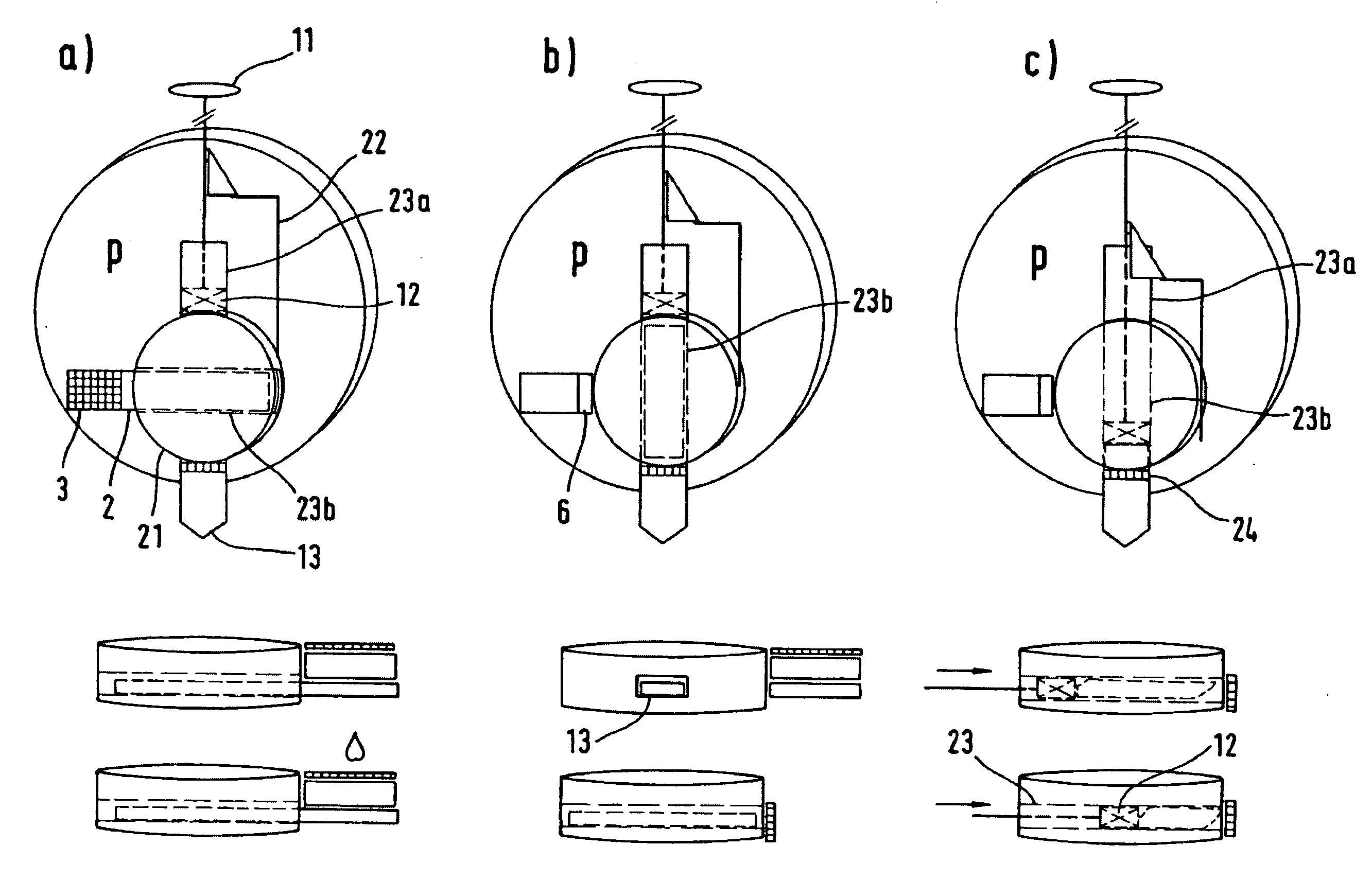
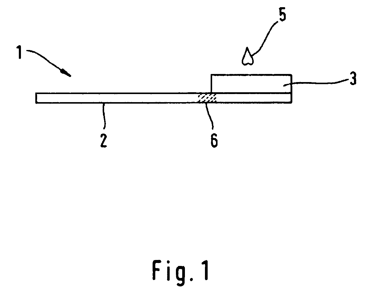
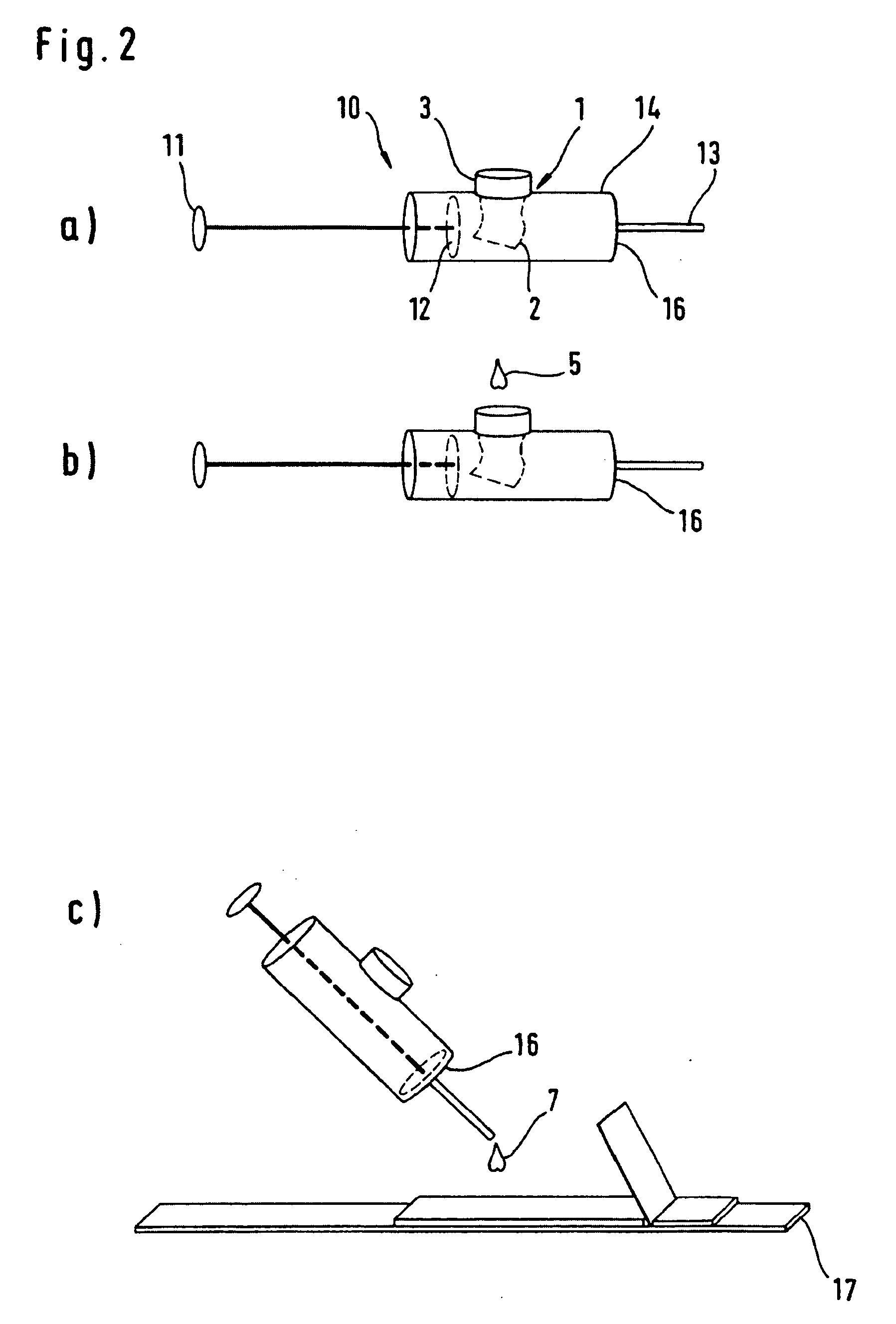
[0043]Referring initially to FIG. 1, an example of the construction of a separation element (1) in accordance with one embodiment of the present invention, is illustrated. The separation element (1) comprises a transport fleece (2) which, for example, consists of glass fibers. A separation fleece (3) which is composed of a filter medium is mounted on the transport fleece (2). The main difference between the transport and the separation fleece is their different densities. In the prior art a density of 77 g / cm2 is, for example, given for a separation fleece and 53 g / cm2 for a transport fleece (Whatman fleece). The smaller thickness of the transport fleece allows a rapid transport of the sample along the fleece whereas the larger thickness of the separation fleece ensures a reliable separation of plasma from blood. When a blood drop (5) is applied, the blood enters the separation fleece (3). The filter medium in the separation fleece separates the blood components from the plasma and ...


PUM

PropertyMeasurementUnit
volumeaaaaaaaaaa
volumeaaaaaaaaaa
volumeaaaaaaaaaa

Abstract

The invention concerns plasma separation on a microliter scale. The method / system according to the invention is able to provide plasma in the range of several microliters within a very short time as it is required, for example, in modern analyses by carrier-bound test elements. Plasma separation and plasma release is carried out in two separate consecutive steps of the method using the device according to the invention such that hemolysis during plasma separation can be avoided despite an accelerated procedure. The device comprises a disposable unit in which the device is characterized by an economical and simple method of production.

Description

BACKGROUND OF THE INVENTION[0001]The present invention relates to plasma collection and, more particularly, to a device and method for separating and discharging plasma. The field of plasma collection plays an important role in analytical methods for determining a concentration of blood components. In many cases such blood tests cannot be carried out with whole blood since this contains corpuscular components (blood cells) which could result in an interference of the assay procedure. Hence, in order to carry out many analytical methods it is necessary to firstly isolate plasma from whole blood, which plasma should be as free as possible from cellular material.[0002]A conventional method for isolating plasma for blood tests is the centrifugation procedure in which cellular components of the blood are separated on the basis of centrifugal forces. This method is laborious and is especially unsuitable when only small amounts of plasma are required for an analysis. However, particularly ...

Claims


Application Information

Patent Timeline
Patent Type & Authority Applications(United States)
IPC IPC(8): A01N1/02C12M1/00G01N33/48B01L3/00B01L9/00G01N1/10G01N1/28G01N33/49
CPCB01L3/5023B01L9/52B01L2300/0681B01L2300/0825Y10T436/2575B01L2400/0481G01N33/491Y10T436/255Y10T436/25375B01L2400/0406
Inventor FREY, GUENTERLADIGES, NORBERTNOETZEL, SIEGFRIEDROESICKE, BERND
Owner ROCHE DIAGNOSTICS OPERATIONS INC
Why Eureka
Try Eureka