Duplex control structure of toy gun

a toy gun and control structure technology, applied in the direction of compressed gas guns, white arms/cold weapons, weapons, etc., can solve the problems of lack of product competitiveness on the market, lack of enjoyment in the structure of one toy gun, etc., and achieve the effect of more variation and enjoyment in playing

Inactive Publication Date: 2011-07-12
YANG CHUNG KUAN
View PDF16 Cites 15 Cited by
  • Summary
  • Abstract
  • Description
  • Claims
  • Application Information

AI Technical Summary

Benefits of technology

The primary objective of the invention is to provide a duplex control structure of toy gun having both of the manually and electrically driving methods to provide the user more variation and enjoyment in playing the toy gun.

Problems solved by technology

This kind of structure of the toy gun lacks of enjoyment while one is playing on the gun since it has only the function of a single shooting.
Nevertheless, as far as the current products are concerned, the way of driving exists only in a single state no matter whether it is a manual or electric motor's driving, and there are no such kinds of structure having both the manually and electrical motor's driving types of today.
Consequently, the fact that the electrically driving toy gun is unable to function once the electric power is used up forms a demerit upon usage, thereby it lacks product competitiveness on the market.

Method used


Image

  • Duplex control structure of toy gun
  • Duplex control structure of toy gun
  • Duplex control structure of toy gun

Examples


Embodiment Construction

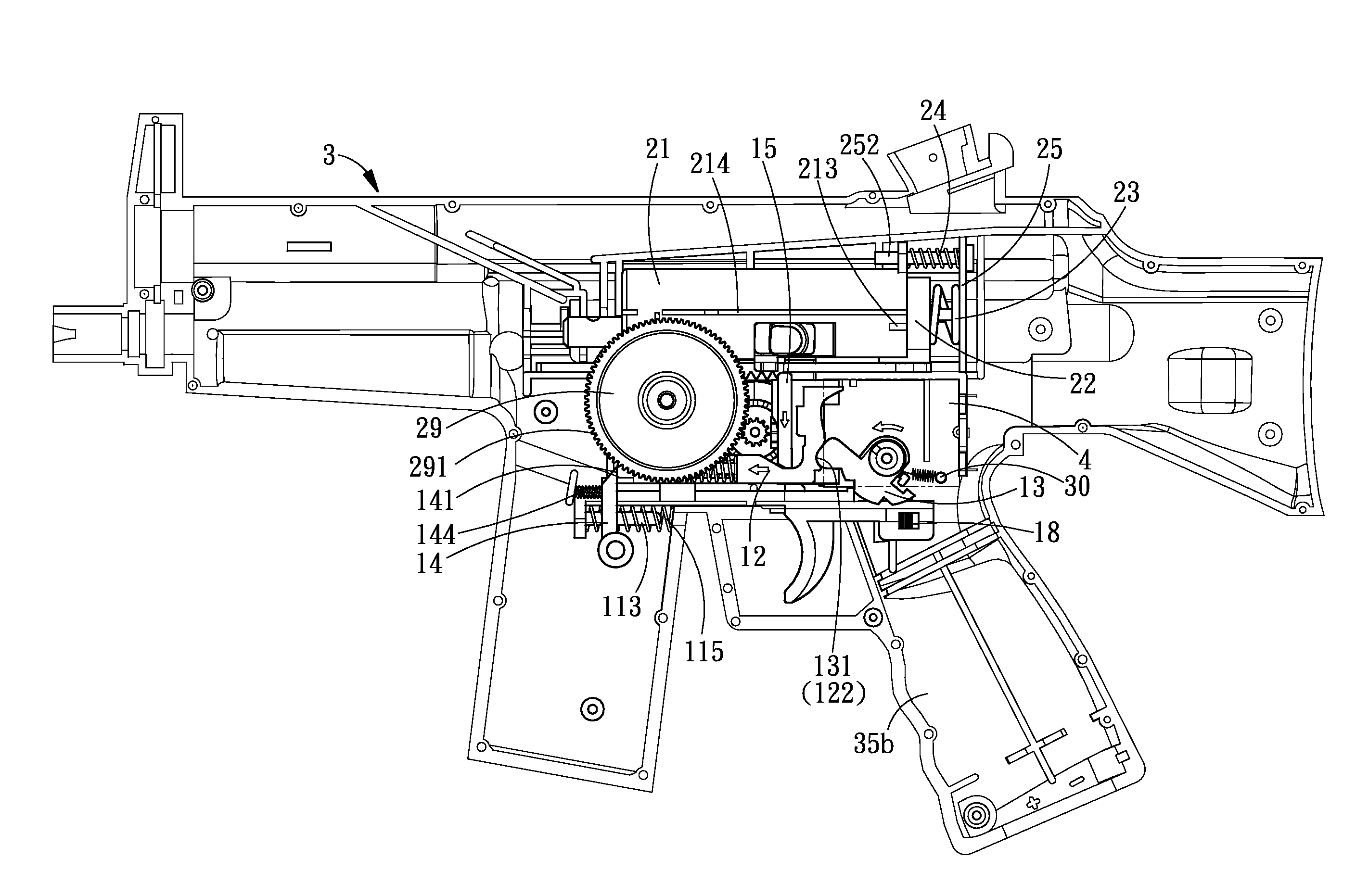
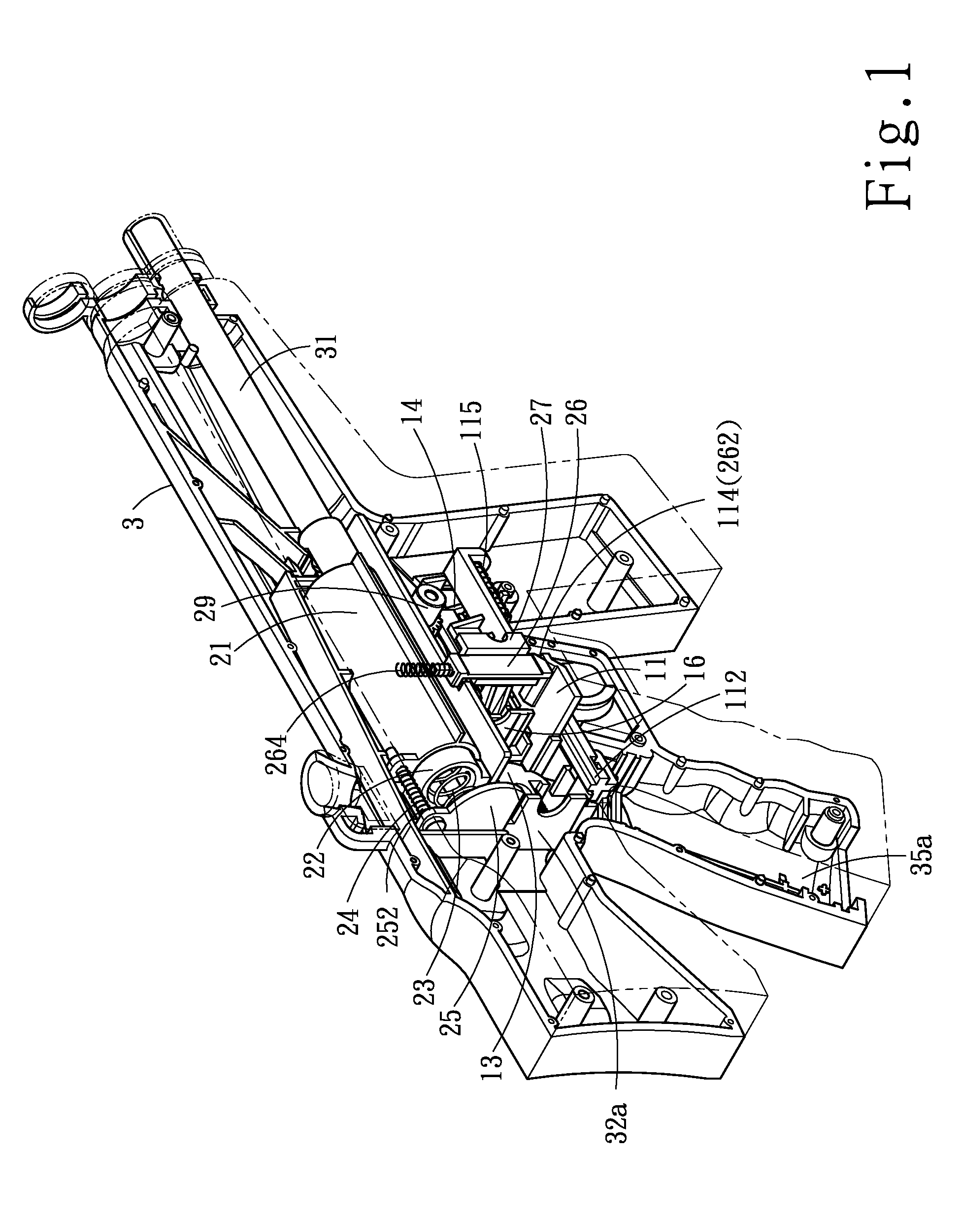
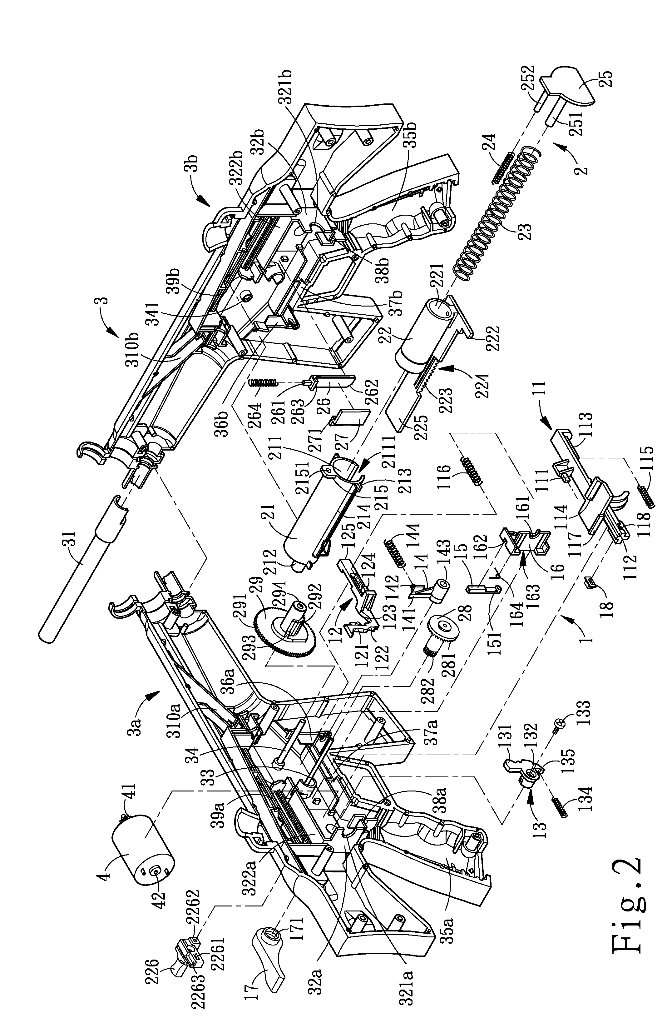
FIG. 1 is an isometric view of the preferred embodiment of the assembled duplex control structure of toy gun of the invention; FIG. 2 is an exploded view of the preferred embodiment of toy gun of the invention; FIG. 3 is a fragmentary cross-sectional view (I) of the preferred embodiment of the assembled manually driving toy gun structure of the invention; FIG. 4 is a fragmentary cross-sectional view (II) of the preferred embodiment of the assembled manually driving toy gun structure of the invention; FIG. 5 is a fragmentary cross-sectional view (III) of the preferred embodiment of the assembled manually driving toy gun structure of the invention. As shown in FIG. 1, FIG. 2, FIG. 3, FIG. 4, and FIG. 5, the duplex control structure of toy gun of the invention includes a main body (3), a control portion (1), a transmission portion (2), and a motor (4).

The main body (3) consisting of a left and right main bodies (3a), (3b) has a barrel (31) provided at the bullet outlet and a fastening ...


PUM


Abstract

A duplex control structure of toy gun includes a main body (3), a control portion (1), a transmission portion (2), and a motor (4). The main body (3) further consists of a left and right main bodies (3a), (3b), a barrel (31), two motor's positioning plates (32a) and (32b), a multiplicity of supporting shaft rods (33), (34), a left and right handle portions (35a), (35b), check plates (36a), (36b), and two sliding ways (37a), (37b). The control portion (1) further consists of a trigger (11), a control rod (12), a propping up plate (13), a brake (14), a slider rod (15), a positioning plate (25), a pull knob (17), and a power switch (18). The transmission portion (2) consists of a gun machine socket (21), a piston (22), springs (23), (24), a positioning plate (25), a check piece (26), a clip piece (27), a small transmission gear (28), and a large transmission gear (29). The motor (4) is connected to a DC power supply. By making use of the pull knob (17) to drive the propping up plate to press against or separate from the corresponding control rod (12) in accommodating the action of the positioning plate (25) of the control portion (1), the invention is capable of achieving the objective of duplex driving functions of a manually and electrically shooting toy gun.

Description

BACKGROUND OF THE INVENTION1. Field of the InventionThe invention relates to a duplex control structure of toy gun, and more particularly, to a duplex control structure of toy gun having both manually and electrically driving modes.2. Description of the Prior ArtAmong the current common toy gun products having projectile plastic (PP) bullet, there are manual and electrical types of structure. The electric type of toy gun makes use of a motor for driving the piston to perform reciprocating motion in a cylinder for propelling a piston to generate high-pressure air for projecting off the plastic bullets. However, the manual type of toy gun makes use of the resilient spring force released from the compressed spring for propelling a piston to generate high-pressure air for projecting off the plastic bullets. These two types of structure are significantly different since their power sources are different.As far as the structure of the manual type of toy gun is concerned, a relatively simp...

Claims


Application Information

Patent Timeline
Patent Type & Authority Patents(United States)
IPC IPC(8): F41B11/00
CPCF41B11/642F41B11/646
Inventor YANG, CHUNG-KUAN
Owner YANG CHUNG KUAN
Why Eureka
Try Eureka