Ink circulation type inkjet printer

a circulation type and inkjet printer technology, applied in the direction of printing, other printing apparatus, etc., can solve the problems of inability to achieve appropriate pressure, variation in pressure, and ink circulation, so as to suppress excessive flow rate, suppress excessive variation in pressure of positive pressure space, and suppress excessive flow rate

Active Publication Date: 2016-03-01
RISO KAGAKU CORP
View PDF3 Cites 8 Cited by
  • Summary
  • Abstract
  • Description
  • Claims
  • Application Information

AI Technical Summary

Benefits of technology

[0019]With the configuration described above, it is possible to suppress excessive increase in the flow rate of the air that flows out from the positive pressure space through the positive-pressure-side pressure regulation path, and thus excessive variation in the pressure of the positive pressure space is suppressed. In addition, it is possible to suppress excessive increase in the flow rate of the air that flows into the negative pressure space through the negative-pressure-side pressure regulation path, and thus excessive variation in the pressure of the negative pressure space is suppressed.

Problems solved by technology

A positive pressure is applied to the positive pressure tank and a negative pressure is applied to the negative pressure tank, thereby causing circulation of ink.
However, during circulation of ink, a variation in the liquid levels of ink of the positive pressure tank and the negative pressure tank causes a variation in the pressures of the positive pressure tank and the negative pressure tank.
Consequently, due to a variation in the nozzle pressure, an appropriate pressure may not be achieved.
However, in the case of suppressing a pressure variation by using the positive pressure tank and the negative pressure tank provided with sufficiently increased air capacities, the space in the device may not be reserved and the sufficient air capacities may not be provided, and thus the pressure variation may not be sufficiently suppressed.
If the setting pressures are high, it may be difficult to satisfy the need.
Therefore, with the various technique described above, a variation in the nozzle pressure due to liquid level variation in the ink tank may not be suppressed.

Method used


Image

  • Ink circulation type inkjet printer
  • Ink circulation type inkjet printer
  • Ink circulation type inkjet printer

Examples


Embodiment Construction

[0025]In the following detailed description, for purposes of explanation, numerous specific details are set forth in order to provide a thorough understanding of the disclosed embodiments. It will be apparent, however, that one or more embodiments may be practiced without these specific details. In other instances, well-known structures and devices are schematically shown in order to simplify the drawing.

[0026]Description will be hereinbelow provided for an embodiment of the present invention by referring to the drawings. It should be noted that the same or similar parts and components throughout the drawings will be denoted by the same or similar reference signs, and that descriptions for such parts and components will be omitted or simplified. In addition, it should be noted that the drawings are schematic and therefore different from the actual ones.

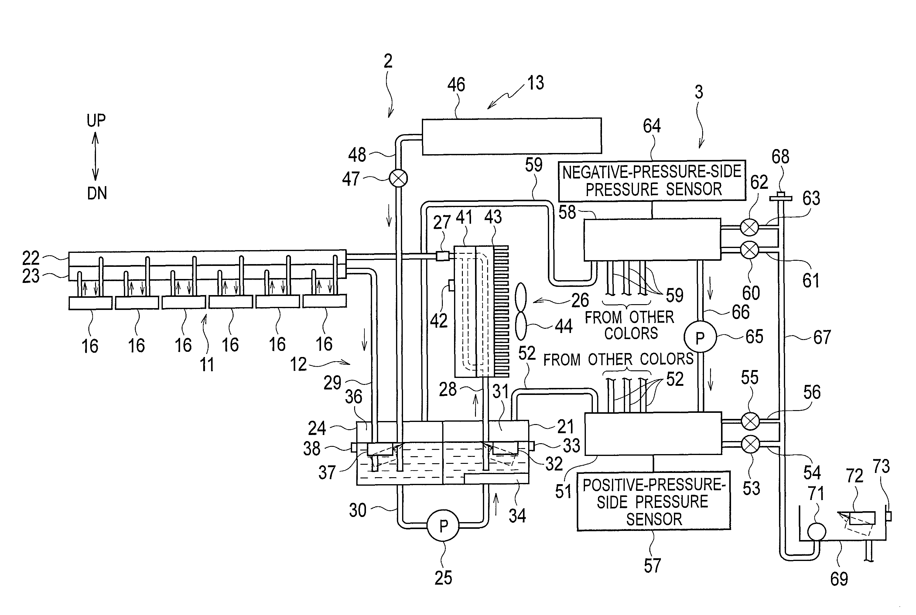
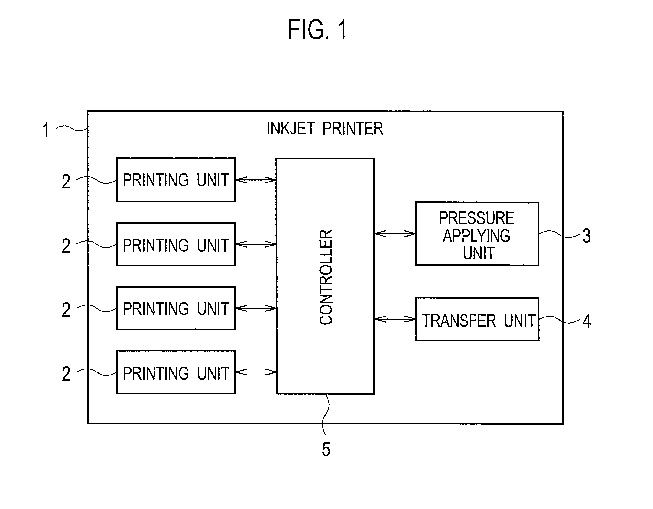
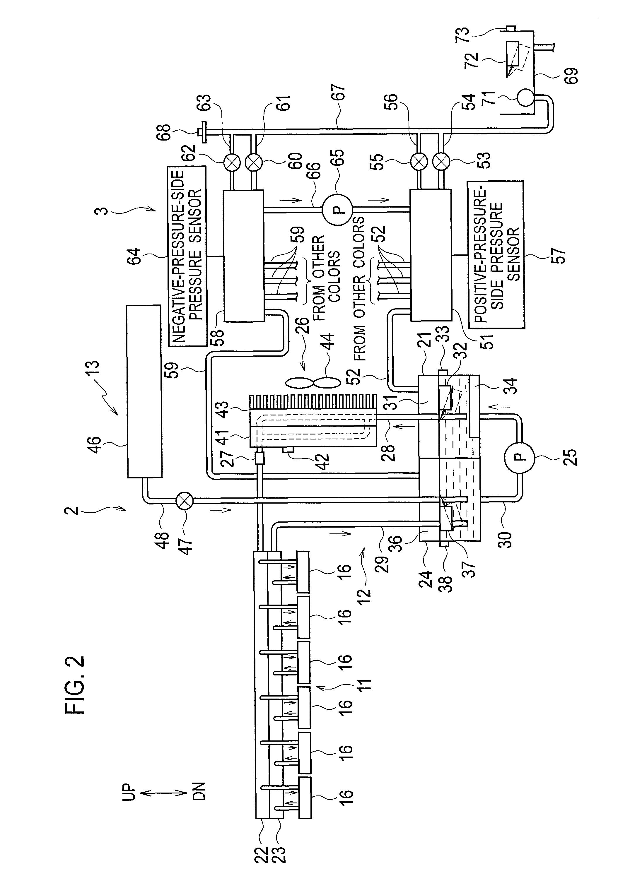
[0027]FIG. 1 is a block diagram illustrating the configuration of an inkjet printer according to an embodiment of the present disclo...


PUM


Abstract

A controller regulates pressures of a positive pressure space and a negative pressure space and maintains the pressures at setting pressures when ink is circulated in a circulation path, by: driving an air pump to apply the setting pressures to the positive pressure space and the negative pressure space; and after the setting pressures are applied, controlling opening and closing of a positive-pressure-side pressure regulation valve, opening and closing of a negative-pressure-side pressure regulation valve, and driving of the air pump according to the pressures in the positive pressure space and the negative pressure space, and opening the positive-pressure-side pressure regulation valve or the negative-pressure-side pressure regulation valve simultaneously with the driving of the air pump.

Description

CROSS REFERENCE TO RELATED APPLICATION[0001]This application is based upon and claims the benefit of priority from the prior Japanese Patent Application No. 2014-192313, filed on Sep. 22, 2014, the entire contents of which are incorporated herein by reference.BACKGROUND[0002]1. Technical Field[0003]The disclosure relates to an ink circulation type inkjet printer.[0004]2. Related Art[0005]Japanese Unexamined Patent Application Publication No. 2008-162262 describes an ink circulation type inkjet printer that performs printing by ejecting ink from an inkjet head while circulating the ink.[0006]The ink circulation type inkjet printer includes an inkjet head, a positive pressure tank disposed upstream of the inkjet head, and a negative pressure tank disposed downstream of the inkjet head. A positive pressure is applied to the positive pressure tank and a negative pressure is applied to the negative pressure tank, thereby causing circulation of ink. The pressures of the positive pressure ...

Claims


Application Information

Patent Timeline
Patent Type & Authority Patents(United States)
IPC IPC(8): B41J2/175
CPCB41J2/17596B41J2/175B41J2/17556B41J2/18B41J29/377
Inventor SUGITANI, HIROSHIAKIYAMA, TOMOYUKIMATSUSHIMA, ISAO
Owner RISO KAGAKU CORP
Why Eureka
Try Eureka