
Ball valve cartridge for use with remote handle

a technology of remote handle and valve body, which is applied in the direction of water supply installation, drawing-off water installation, transportation and packaging, etc., can solve the problems of limiting the flow rate of ceramic valve elements, affecting the operation of the unit, and affecting the operation of the valve body, so as to limit the rotational movement and increase the freeze resistance of the hydrant

Active Publication Date: 2011-07-12
EASTERN VIRGINIA MEDICAL SCHOOL
View PDF5 Cites 9 Cited by
  • Summary
  • Abstract
  • Description
  • Claims
  • Application Information

AI Technical Summary

Benefits of technology

[0009]The instant invention is based upon the discovery of a new ball valve and, specifically, one that is contained within a cartridge so that it can be positioned remotely from a handle or other actuating element. The cartridge contains a ball valve element and an internal stem with a key for rotating the ball valve element between open and closed positions. The stem has rotational stop elements that cooperate with rotational stops inside the cartridge to limit rotational movement of the stem and the ball valve element. In a yard hydrant application, a drain valve can be added to regulate the opening and closing of the drain hole in cooperation with the water valve operation. The cartridge itself is very compact and permits the positioning of the ball further from the actuator than prior art ceramic disk cartridges, thereby increasing the freeze resistance of a hydrant including the ball valve cartridge.

Problems solved by technology

That makes this unit subject to failure due to spring failure, as well as failure of the disks themselves.
Ceramic has a very different co-efficient of expansion than steel and brass and copper and, in extreme temperatures such as those encountered in the freezeless application under consideration, this may lead to failure, as well.
Ceramic disk cartridges can retain water so that freezing may lead to catastrophic failure.
Flow rate is also limited in ceramic valve elements by size limitations imposed by the ceramic material itself.
Ceramic disk valve elements are more prone to sediment blockage than ball valve elements.
Generally speaking, the machining of ceramic parts can leave flaws which can cause premature failure of those parts.
Because ceramics are so hard, mating surfaces tend to wear more quickly than mating surfaces of parts made from other materials.
The hardness of ceramics makes them generally more difficult to machine.
Ceramics require more expensive abrasive materials and must be machined more slowly than metal to avoid damage.

Method used


Image

  • Ball valve cartridge for use with remote handle
  • Ball valve cartridge for use with remote handle
  • Ball valve cartridge for use with remote handle

Examples


Embodiment Construction

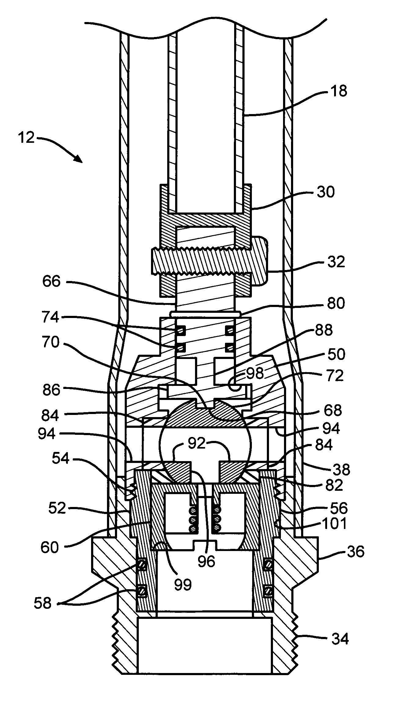
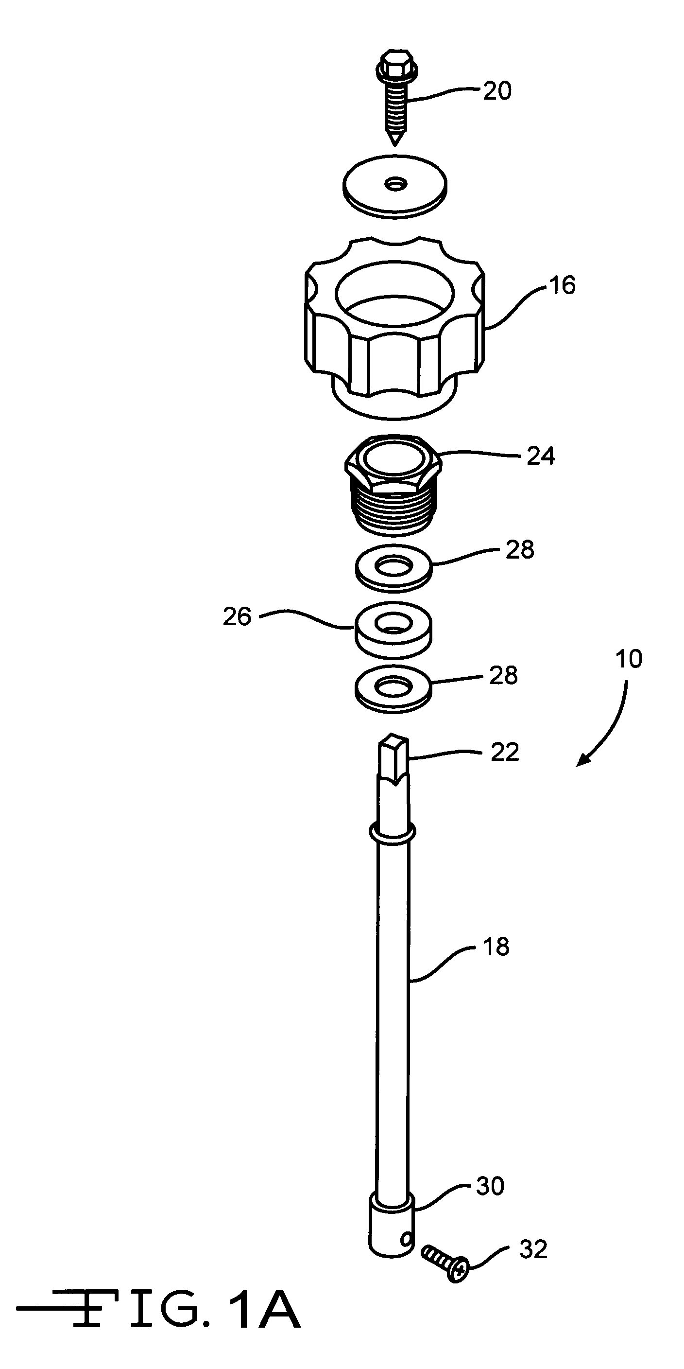
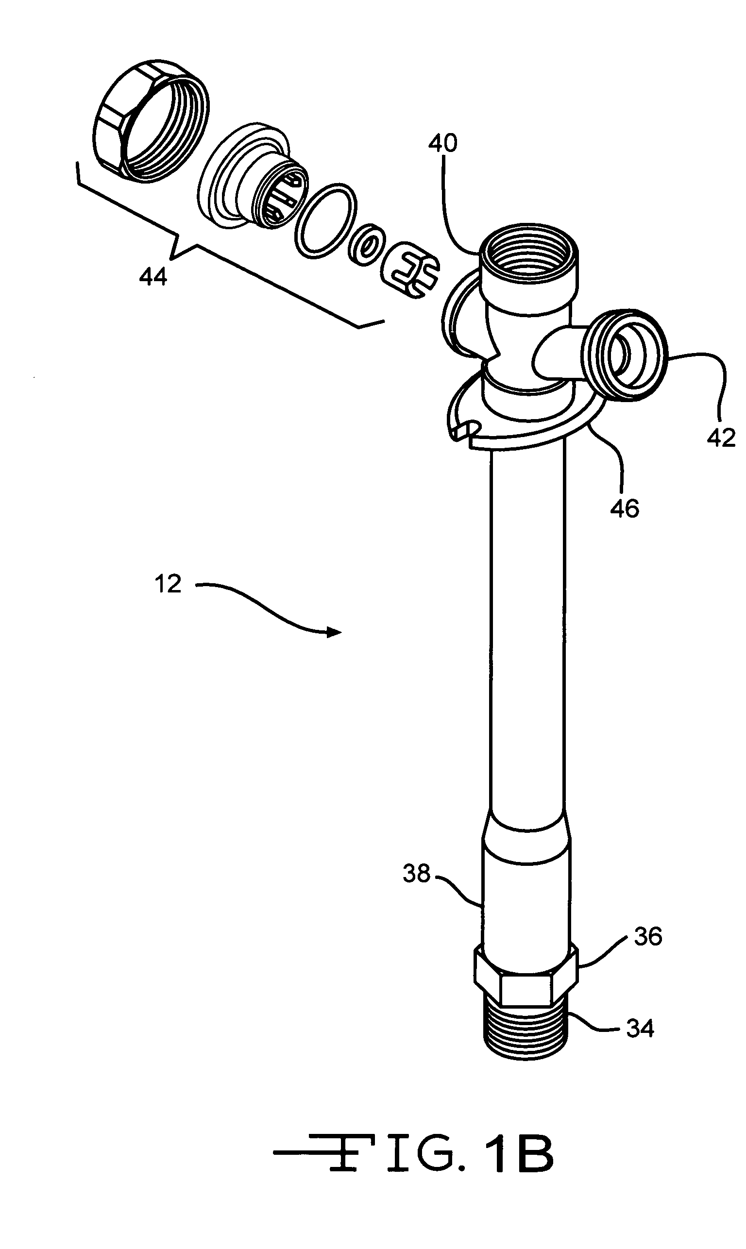
[0029]Referring now in more detail to the drawing figures, a freezeless sillcock according to the invention comprises an actuator indicated generally at 10 in FIG. 1A, a sillcock tube indicated generally at 12 in FIG. 1B and a ball valve cartridge indicated generally at 14 in FIG. 1C. The actuator 10 comprises a handle 16 (FIG. 1A) which is drivingly connected to a stem 18 by a fastener 20. Torque imparted to the handle 16 is transmitted to the stem 18 through torque surfaces 22 on the stem 18 which are engaged by corresponding surfaces (not shown) on the handle 16. A packing nut 24, packing 26 and washers 28 secure the stem 18 within the sillcock tube 12 (FIG. 1B). At the distal end 30 (FIG. 1A) of the stem 18, a torque transmitting element is provided for transmitting torque from the stem 18 to the cartridge 14. The torque transmitting element shown is a fastener 32 although any torque transmitting element will suffice.

[0030]The sillcock tube 12 (FIG. 1B) is threaded as indicated ...


PUM


Abstract

A ball valve cartridge is disclosed. It is especially well suited for freezeless hydrant applications and any other application where it is positioned remotely from a handle or other actuating element. The cartridge contains a ball valve element and an internal stem with a key for rotating the ball valve element between open and closed positions. The stem has rotational stop elements that limit rotational movement of the stem and the ball valve element. In a yard hydrant application, a drain valve can be added to regulate the opening and closing of the drain hole. It has an operational range of a quarter turn or ninety degrees.

Description

BACKGROUND OF THE INVENTION[0001]1. Field of the Invention[0002]The present invention is a ball valve cartridge especially adapted for use in applications where it is actuated by a remotely positioned handle, such as in freezeless wall hydrants or faucets and yard hydrants.[0003]2. Description of the Prior Art[0004]The field of valves for regulating and controlling fluid flow is certainly well developed. Self-draining yard hydrants and freezeless wall faucets, wall hydrants, sillcocks or bibcocks, are also well known.[0005]Yard hydrants are described in many US Patents, including U.S. Pat. No. 4,372,339. Freezeless wall hydrants are also described by many U.S. Patents, including my prior U.S. Pat. No. 5,158,105.[0006]A freezeless sillcock with ceramic disk valve elements is described in U.S. Pat. No. 6,880,573. This device has an operating range constituting only one quarter of a turn of an actuator handle. However, the components of the ceramic disk are contained within a cartridge...

Claims


Application Information

Patent Timeline
Patent Type & Authority Patents(United States)
IPC IPC(8): E03B9/02
CPCE03B9/025E03B9/14Y10T137/5392Y10T137/5497Y10T137/7613Y10T137/88054
Inventor CONWAY, SCOTT T.
Owner EASTERN VIRGINIA MEDICAL SCHOOL
Learn More