

Hinge
- Summary
- Abstract
- Description
- Claims
- Application Information
AI Technical Summary
Benefits of technology
Problems solved by technology
Method used
Image

Examples
Embodiment Construction
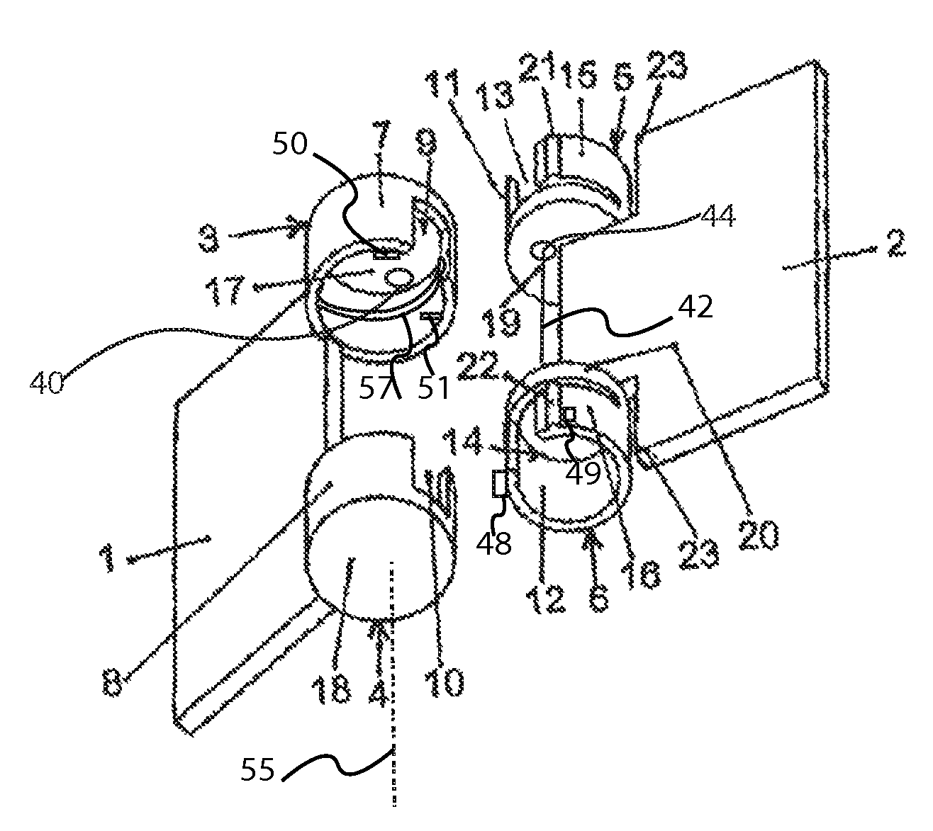
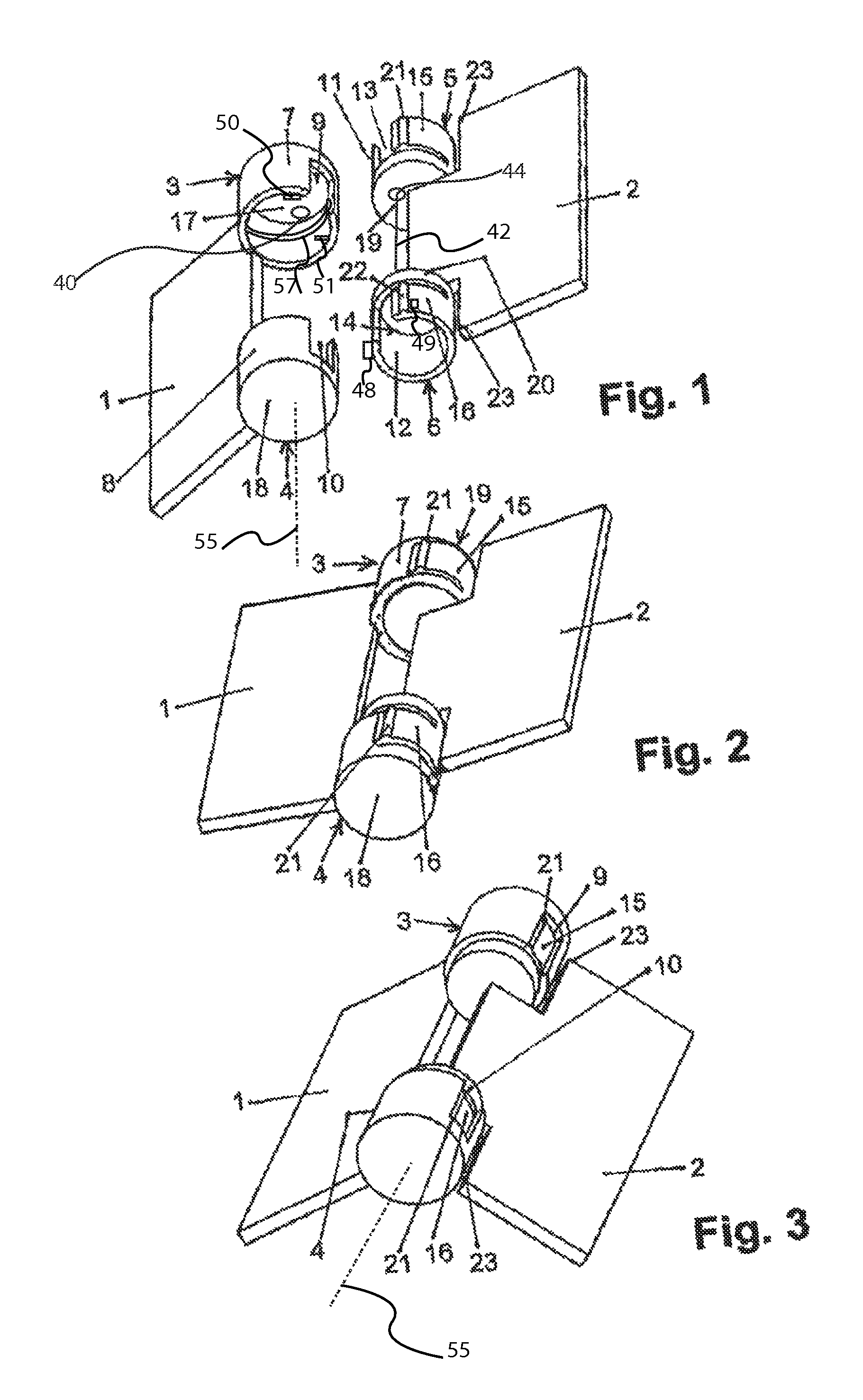
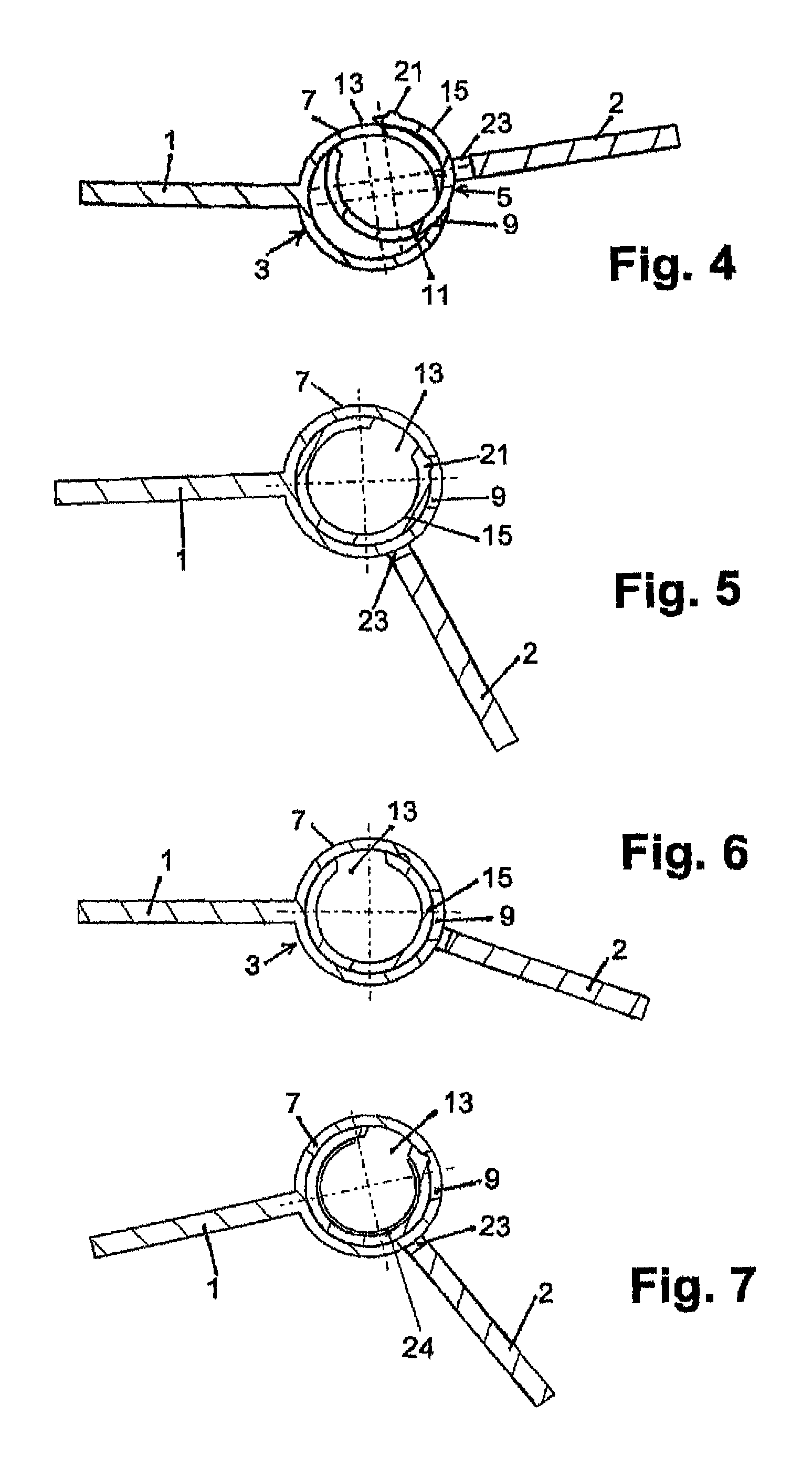
[0028]All figures show a first component 1 of plastics material with integrally formed hinge elements 3, 4, which each consist of a bearing sleeve 7, 8 with respective closed bases 17, 18, the bases being mounted at the opposite ends, and which are provided with longitudinal gaps 9, 10 extending up to the bases. The longitudinal gaps 9, 10 are provided at the first component 1 approximately opposite the fastening sides of the first hinge elements 3, 4. The component is a plastics material molded part which is produced in an injection-molding method and at which the hinge elements 3, 4 are integrally formed. Provided congruently in correspondence with these bearing sleeves 7, 8 at a second component 2 are second hinge elements 5, 6 which are constructed as insertion sleeves 11, 12 and which each have a closed base 19 or 20, which sleeves are so attached opposite to one another to the second component 2 that a guide slot 23 is formed between the circumferential wall and the second com...
PUM
 Abstract
Description
Claims
Application Information