Stripping device for a press

a technology of a stripping device and a press, which is applied in the direction of paper/cardboard containers, containers, container making machinery, etc., can solve the problems of stripping stations that may operate too slowly for use with high-throughput stripping, and the stripping station may be shut down for a significant time, so as to reduce the difficulty and disadvantages, the effect of easy retrofitting and inherent resilience of the stripping devi

Inactive Publication Date: 2008-04-22
QUERCIA PAOLO
View PDF41 Cites 20 Cited by
  • Summary
  • Abstract
  • Description
  • Claims
  • Application Information

AI Technical Summary

Benefits of technology

[0005]The present invention reduces the difficulties and disadvantages of the aforesaid designs by providing a resilient spring-like stripping device, which can be easily retrofitted into an existing pressing machine to strip waste portions from a pre-cut sheet, without the need for complex machinery. The stripping device is constructed from inexpensive materials such as stainless steel. Advantageously, the previously mentioned problems associated with paper jams is significantly reduced or essentially eliminated by the addition of a either a resiliently movable blocking member or a stationary blocking member, which prevent the waste pieces from interfering with a stripping operation. The inherent resilience of the stripping device enables significantly increased stripping speeds, which increases productivity and decreases stoppage time. Furthermore, the device of the present invention significantly reduces pre-press / on-press make ready times.

Problems solved by technology

One problem, however, the stripping stations may operate too slowly for use with a high throughput stripping.
Moreover, paper jams may occur frequently once the waste piece has been removed, thus causing the stripping station to be shut down for a significant time while the jam is removed.

Method used


Image

  • Stripping device for a press
  • Stripping device for a press
  • Stripping device for a press

Examples


Embodiment Construction

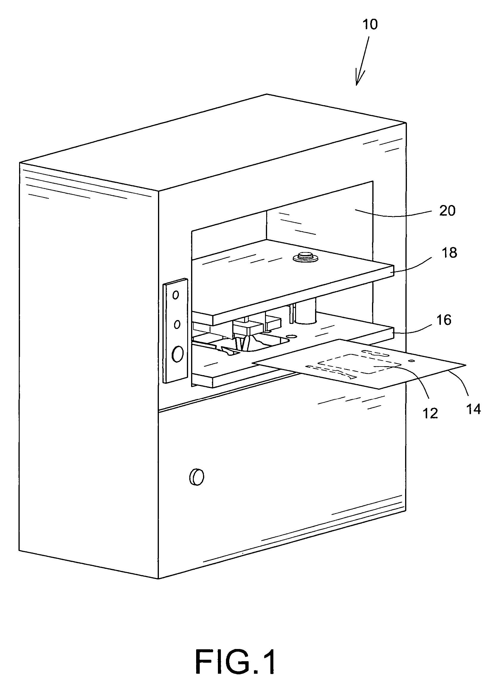
[0028]Referring now to FIG. 1, a paper press for pressing paper products is shown generally at 10. The press 10 is used to remove waste pieces of material 12 from pre-cut sheets of material 14, which is typically paper, paperboard, cardboard and the like. The pre-cut sheet of material 14 is typically a template for many applications. Examples include, but are not limited to, backing sheets for a blister package, blanks for constructing paperboard cartons and the like. The press 10 is a die-cutting press of a conventional design known to those skilled in the art and includes a pair of planar body press frames 16, 18 mounted within a housing 20.

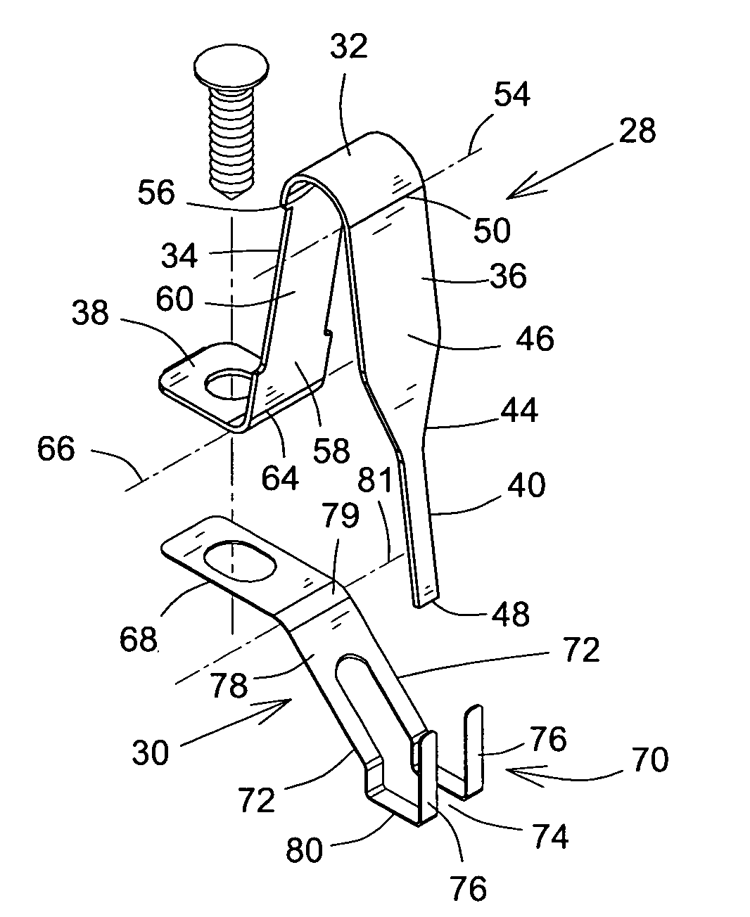
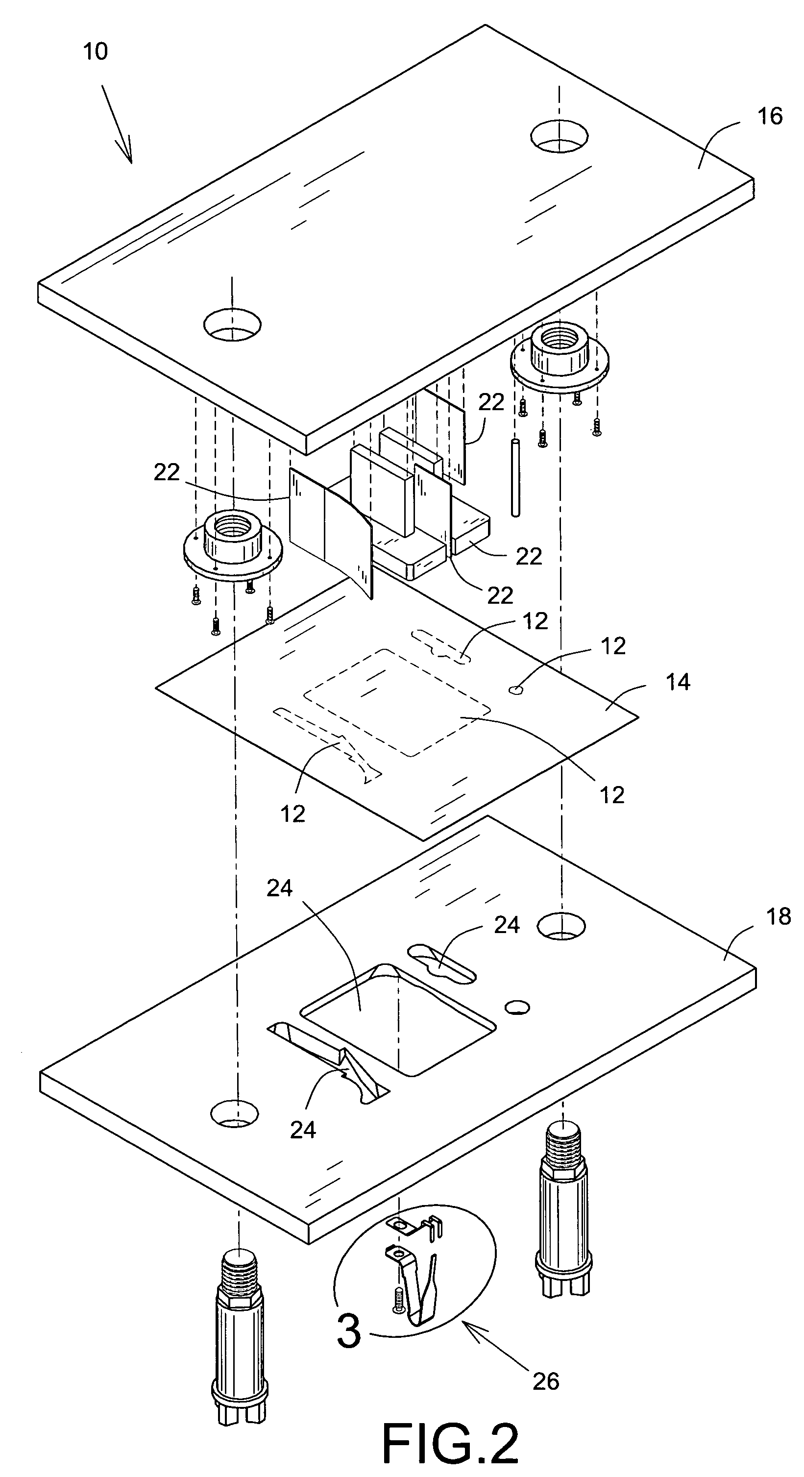
[0029]FIG. 2 illustrates a portion of the frames 16, 18 for ease of viewing. The frame 16 includes a number of pre-shaped male dies (punches) 22; the frame 18 includes a corresponding number of pre-shaped female body openings 24, which are complementary to the male dies 22. The dies 22 and the openings 24 are pre-shaped according to a required ...


PUM

PropertyMeasurementUnit
angleaaaaaaaaaa
lengthaaaaaaaaaa
resilientaaaaaaaaaa

Abstract

A stripping device for stripping a waste piece from a sheet of material, which includes a stripping member with a connecting portion, a supporting finger located on one side of the connecting portion, and a stripping finger located on another side of the connecting portion. The supporting finger has one end connected to a frame and is movable about its end with respect to the frame. The stripping finger has a stripping end portion, which is biased away from the supporting finger and contacts the waste piece at an angle. The supporting finger is deflected away from the waste piece and the stripping end portion is moved further away from the supporting finger and against the waste piece to strip it from the sheet.

Description

CROSS-REFERENCE TO RELATED APPLICATION[0001]The present application is a Continuation-in-part (C.I.P.) of pending U.S. patent application Ser. No. 10 / 819,926 filed on Apr. 8, 2004.FIELD OF THE INVENTION[0002]The present invention concerns mechanical devices, more particularly to mechanical devices for stripping waste from a pre-cut sheet of material.BACKGROUND OF THE INVENTION[0003]Presses for cutting sheet material such as paper, paperboard, cardboard and the like, are well known. When the sheet material is pre-cut and includes pre-cute portions, which need to be stripped out, the presses include stripping stations. One such stripping station is disclosed in U.S. Pat. No. 3,786,731, issued to Bobst et al. on Jan. 22, 1974 for “Press for Cutting Sheet Material”. Bobst discloses stripping stations, which include a pair of frames and a board, which has a series of pre-cut die openings, which are shaped to the desired design. Stripping tools are mounted to the frames and sandwich the w...

Claims


Application Information

Patent Timeline
Patent Type & Authority Patents(United States)
IPC IPC(8): B26F3/00B26D7/18B26F1/00B31B50/00
CPCB26D7/1818B26D2007/1881B26D2007/189B31B70/00Y10T83/2096Y10T83/217Y10T225/30B31B50/00
Inventor QUERCIA, PAOLO
Owner QUERCIA PAOLO
Why Eureka
Try Eureka