
Fault tolerant optical apparatus

a technology of optical apparatus and fault tolerance, applied in electromagnetic transmission, remote controlled aircraft, transmission, etc., can solve the problems of limiting aircraft availability and profitability, system failure, and increasing weight at the expense of payload, so as to improve bandwidth, enhance light diffusion and scattering, and resist emp aggression. inherent resilien

Active Publication Date: 2018-09-06
CHRETIEN PASCAL
View PDF0 Cites 2 Cited by
  • Summary
  • Abstract
  • Description
  • Claims
  • Application Information

AI Technical Summary

Benefits of technology

The patent text describes a new technology that uses a special polymer film to improve optical communication in aircraft. This technology helps to protect against damage and also increases the bandwidth of the optical signal. This can be especially useful in composite airframes, where the polymer film can be easily integrated. The technology also eliminates the need for complex wiring looms, which can improve system reliability and resistance to damage. The polymer film contains macromolecules and doping elements that enhance light diffusion and scattering in the material.

Problems solved by technology

Wiring looms ageing, resulting from mechanical, electrochemical and thermal stresses, is a known source of system failure.
This well-known weakness was proven to be the cause of a number of crashes (such as TWA 800).
Moreover, military aircrafts require ballistic impact resilience imposing redundant electrical cablings, following different paths, subsequently adding weight at the expense of payload, as well as complicating maintenance operations.
On an aeronautical standpoint, wiring faults are a recurrent cause of unscheduled maintenance, limiting aircraft availability and profitability.
However, the use of metal shielding, dissipative EMP protection and filtering make EMP hardened cablings significantly heavier than conventional wiring.
Data lines are the most vulnerable to EMP aggression and Electrostatic Discharges (ESD) as they carry small signals and connect to the most sensitive and fragile components.
To some extent, any conventional wiring is a cause of intrinsic electromagnetic weakness both on a radiated emission and radiated susceptibility stand points.
Referring to modern electric, or hybrid-electric drive trains, copper and / or aluminum, based wiring is a known weakness, when integrated on aircrafts.
One of the main limitations of those electric propulsion systems resides in their poor electromagnetic compatibility with the surrounding environment: Fast switching power circuitry (such as IGBT and / or MOSFETS) commonly used in motor controller in order to minimize power losses is one cause of electromagnetic compatibility problem.
Such circuitry produces high order harmonics, hence significant interference with surrounding avionics and onboard electronic systems.
The former refers to free space propagation of electromagnetic radio waves, whereas the later refers to electromagnetic signals propagating along the power lines and data cables, potentially disturbing the operation of aircraft's systems.
If those, somewhat heavy, fixes can mitigate the detrimental effect of conducted emissions, they negatively impact system's weight.
However, optical fibers and their associated connectors are traditionally quite fragile, require large bending radius and can become heavy when mechanically reinforced to survive battle damages.
Another limitation of optical fibers is the inherent susceptibility of the connectors to dust ingress, resulting in difficult maintenance on a Theater of Operations.
Considering the high vibration environment found on some military aircrafts, connecting many subsystems in star and spur topologies to the aircraft's flight computer, through a network of multiple conventional optical fibers drastically increases the number of connectors and optical interface and is not a recommended option due to high production cost and statistically reduced reliability.
Besides, those systems still suffer from obvious vulnerabilities to ballistic damages as star and spur topologies are intrinsic sources of Single Point Of Failure.
Consequently, redundant routes are necessary (in the same manner as with copper wiring) which negatively impacts weight budget.
However, those inherently complex and heavy systems are expensive and difficult to transfer to UAV operating on the battlefield.
Furthermore, they revolve around inherently centralized computer units suffering from intrinsic ballistic impact weakness.
However, conventional wiring suffers from inherent bandwidth limitation, hence limited data speed capability.
As high-capacity networking is required in the context of distributed processing, the need for high speed data transmission is stretching data carrying capacity of copper based wiring looms to their limit.
Bandwidth limitation of conventional wiring has direct consequence on the backhaul architecture used to interconnect sub-systems: traditionally, star and spurs topologies are the preferred option as they offer the better capacity, but at the expense of fault protection capability.
However, they are difficult to implement in the context of distributed processing due to their inherent bandwidth limitation.
Those patents address the transmission of light signals through a polymer film; however, none of them provide a solution to network isolation, distributed processing and ballistic impact resilience.
In particular, the directional solution disclosed by US20040114854 (OUCHI) increases vulnerability to the effects of ballistic damages.

Method used


Image

  • Fault tolerant optical apparatus
  • Fault tolerant optical apparatus
  • Fault tolerant optical apparatus

Examples


Embodiment Construction

[0055]The following detailed specification is exemplary in nature and is not intended to limit the disclosure or the application and uses of the embodiments of the disclosure. Descriptions of specific devices, techniques, and applications are provided only as examples. As would be apparent to one of ordinary skill in the art after reading this specification, the following are examples and embodiments of the disclosure and are not limited to operating in accordance with these examples. Other embodiments may be used and structural changes may be made without departing from the scope of the exemplary embodiments of the present disclosure.

[0056]Embodiments of the disclosure may be described herein in terms of functional and / or logical block components and various processing steps. It should be appreciated that such block components may be realized by any number of hardware, software, and / or firmware components configured to perform the specified functions. For the sake of brevity, conve...


PUM


Abstract

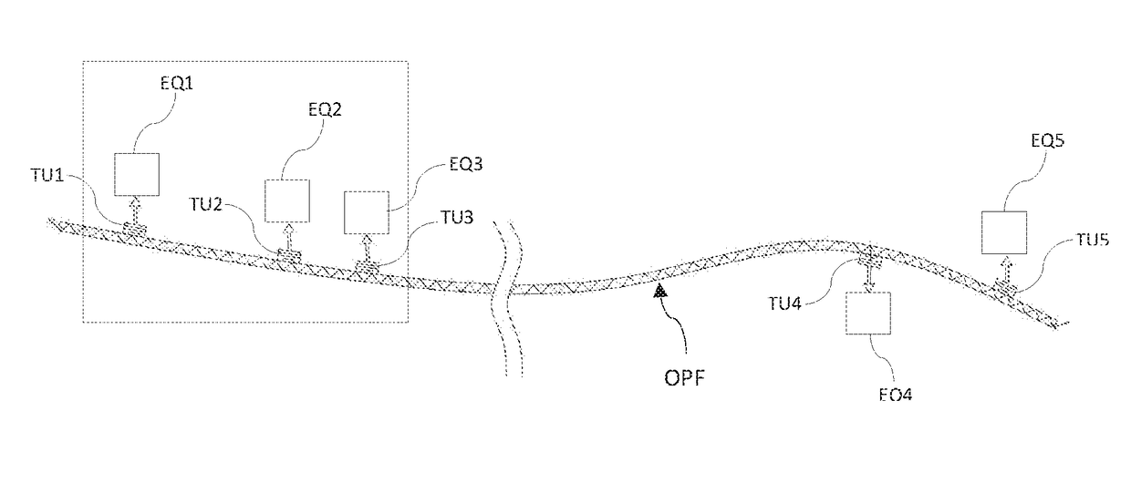
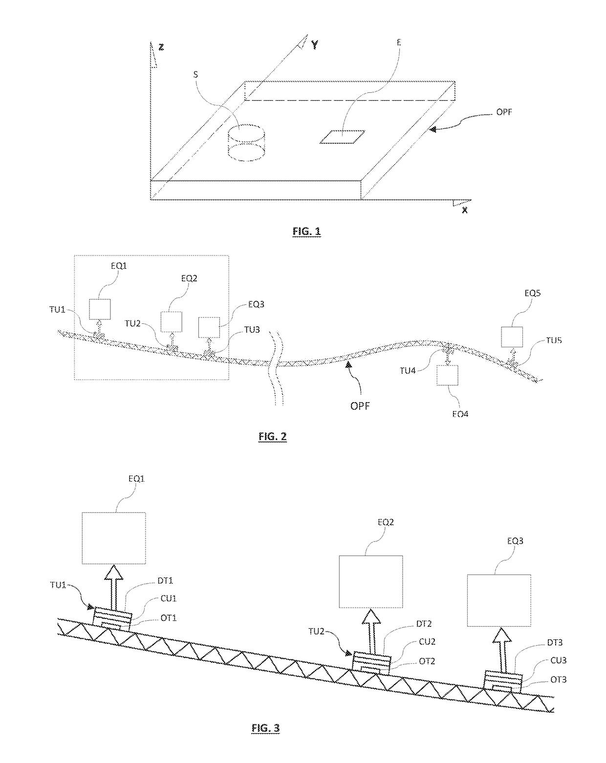
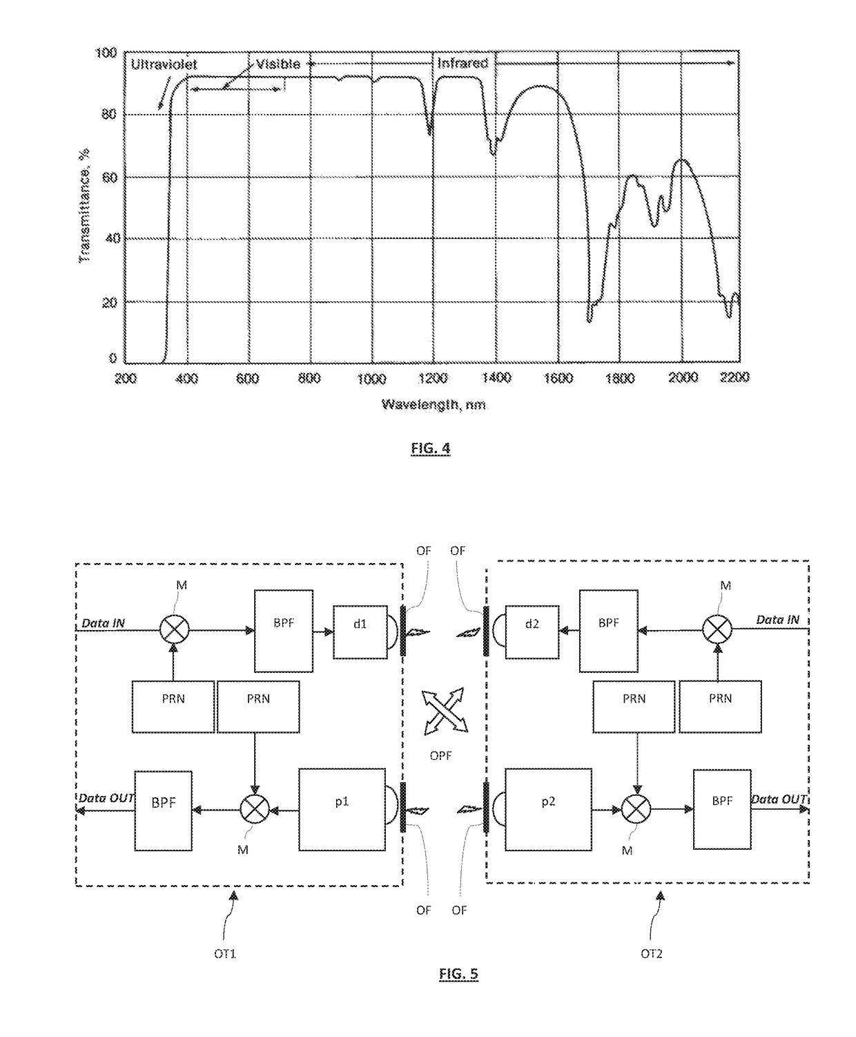
A fault tolerant optical apparatus resilient to ballistic impact damages, capable of enabling distributed processing and networking and using the spectrophotometric transmission properties of polymer film.

Description

TECHNICAL FIELD OF THE INVENTION[0001]The object of the invention is a fault tolerant optical apparatus enabling distributed processing through the interconnection of multiple electronic systems, capable providing high speed data communication, multiple networking and distributed processing as well as being resilient to ballistic damages and EMP agressions. Said optical apparatus comprising an optically transparent polymer film enabling light propagation deployed throughout the vehicle and capable of providing optical communication between a plurality of optical transceiver interfaces connected to subsystems such as (but not limiting to) avionics and flight control systems. Said optical apparatus being capable of enabling a plurality of distinct and mutually isolated networks sharing the same transmission medium. The purpose of the disclosed optical apparatus is to be capable of providing provide ballistic impact resilience and EMP (Electromagnetic Pulse) and ESD (Electrostatic Disc...

Claims


Application Information

Patent Timeline
Patent Type & Authority Applications(United States)
IPC IPC(8): H04J14/02G02B6/122G02B6/42B64C39/02
CPCH04B10/802H04B10/803H04J14/028H04J14/0256B64C39/024H04J14/0284G02B6/42G02B6/1221G02B1/045G02B6/10B64U2201/20
Inventor CHRETIEN, PASCAL
Owner CHRETIEN PASCAL
Learn More