
Projection screen having a plural number of light control layers

a technology of projection screen and light control layer, which is applied in the direction of instruments, machines/engines, transportation and packaging, etc., can solve the problems of low total light transmittance, dark screen, and insatiable conventional screen

Active Publication Date: 2009-09-08
LINTEC CORP
View PDF31 Cites 0 Cited by
  • Summary
  • Abstract
  • Description
  • Claims
  • Application Information

AI Technical Summary

Benefits of technology

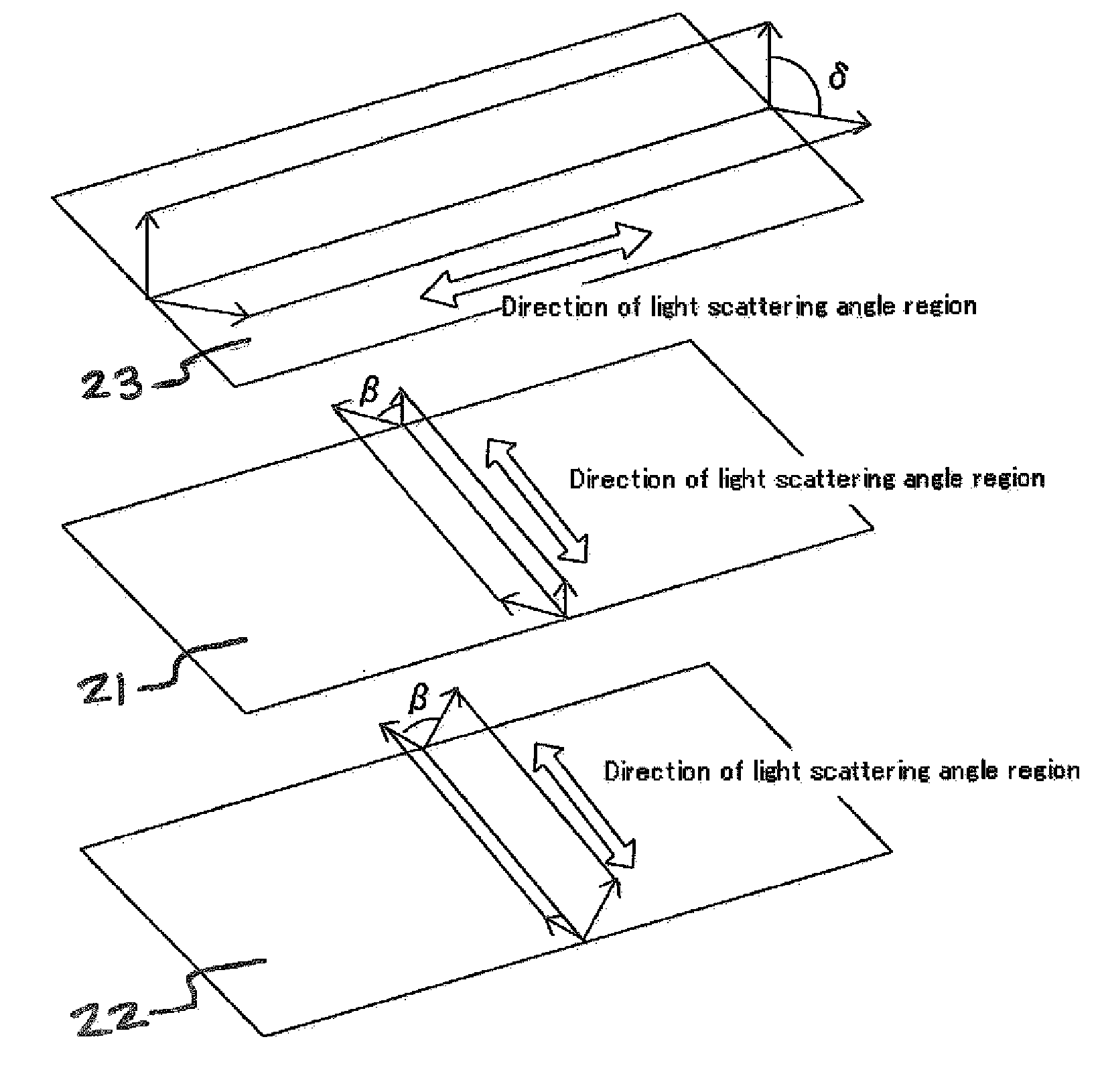
The present invention is a projection screen that uses light control films to achieve high light diffusion and image quality over a wide angle range without deteriorating light transmittance. The screen has multiple layers with different refractive indices that scatter light in a controlled manner. The layers are laminated with their light scattering angle regions nearly parallel or perpendicular to each other. The screen has a high total light transmittance and provides a brighter image at a wide view angle without moiré patterns.

Problems solved by technology

Although a conventional projection screen is superior in light diffusion, total light transmittance is low; therefore a screen becomes dark.
Further, since an angle range providing an image with a high level visibility was narrow, a conventional screen was not satisfactory as a screen used for a large-sized television with a high-level image quality.
However, such screen dose not necessarily satisfy the desire that an image with a high level quality is provided over a wide angle range as a large-sized television.

Method used


Image

  • Projection screen having a plural number of light control layers
  • Projection screen having a plural number of light control layers
  • Projection screen having a plural number of light control layers

Examples


example 1

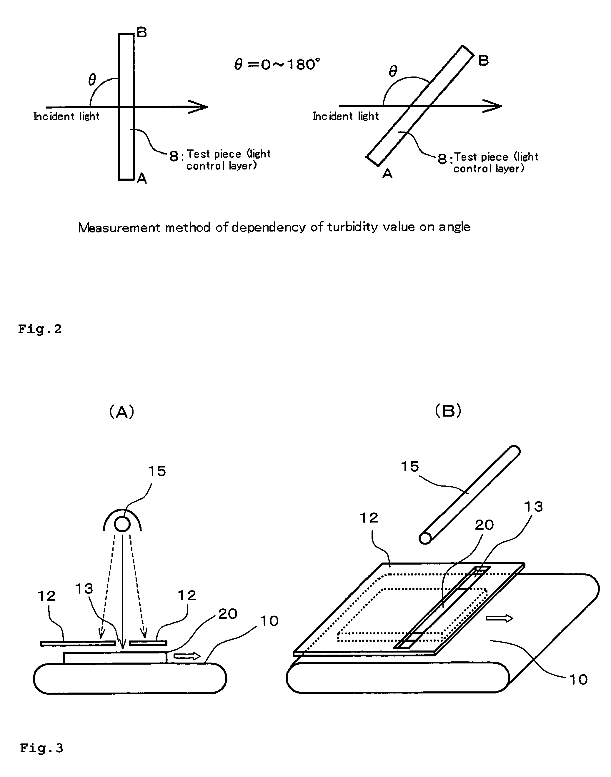
[0052]An optically curing resin composition in which 50 parts of tribromophenoxyethyl acrylate (refractive index: 1.567) and 3 parts of benzyl dimethylketal were added to 50 parts of polyether urethane acrylate (refractive index: 1.481) obtained by reaction of polypropylene glycol having an average molecular weight of about 2000, toluene diisocyanate and 2-hydroxyethyl acrylate was coated on a glass plate at a thickness of about 220 μm. A rod shape high pressure mercury lamp with 80 W / cm was fixed on a position of 120 cm over the coating layer and light was irradiated through a light shielding plate provided with a slit so that light is vertically irradiated on the whole surface of the coating layer while moving a glass plate provided with a coating layer at a speed of 1 m / minute (refer to FIG. 3) to obtain the light control layer (1). The light scattering angle region indicating the haze value of 60% or more was from 74 to 106° (region with a range of 32°). Two light control layer ...

example 2

[0053]Operation was carried out in similar manner as Example 1, except that an interference filter which transmits selectively ultraviolet rays with a wavelength of 313 nm was provided at the irradiation plane of the high pressure mercury lamp, to obtain the light control layer (2). The light scattering angle region indicating the haze value of 60% or more was from 66 to 114° (region with a range of 48°). Two light control layer (2) were used and laminated in the same manner as Example 1 (so that the directions of the respective light scattering angle regions are orthogonal), to obtain a screen.

example 3

[0054]Operation was carried out in similar manner as Example 2, except that the light of the high pressure mercury lamp to the coating layer of the resin composition was irradiated at an angle of 25° from the normal line of the coating layer, to obtain the light control layer (3). The light scattering angle region indicating the haze value of 60% or more was from 90 to 140° (region with a range of 50°). Two light control layer (3) were used, and one remains on the glass plate and the other was peeled from the glass plate and was laminated so that the respective light scattering angle regions are plane symmetry to the parallel plane including normal line to the direction of the light scattering angel region, to obtain the light control layer in which the light scattering angle region indicating the haze value of 60% or more was from 40 to 140° (region with a range of 100°). The light control layer (4) on the glass plate was used as a screen. At this time, it was arranged so that the ...


PUM

PropertyMeasurementUnit
hazeaaaaaaaaaa
angleaaaaaaaaaa
angleaaaaaaaaaa

Abstract

A projection screen using light control layers having high light diffusion and further providing an image with high image quality over a wide angle range without deteriorating light transmittance is provided. A plural number of light control layers in which a haze value of the layer is dependent on an angle and a light scattering angle region showing a haze value of 60% or more is in the range of 30° or more when light is injected on the surface of the layer at an angle of 0 to 180° are laminated to obtain a screen.

Description

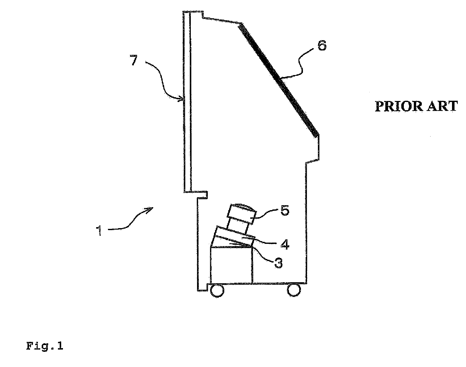
BACKGROUND OF THE INVENTION[0001]1. Field of the Invention[0002]The invention relates to a projection screen.[0003]2. Description of the Related Art[0004]A projection display is also called as rear-projection display and its example is illustrated in FIG. 1. As shown in the FIG. 1, the projection display 1 injects light from a light source unit 3 on a mirror 6 through an image display unit 4 and then projection lens 5, and the light coming through the image display and the projection lens is reflected on the mirror to project an image on a screen 7 from a rear face. A liquid crystal panel, a cathode ray tube (CRT) and the like are used for the image display unit 4. Further, there is also a system of directly projecting an image from the image display unit on a screen.[0005]A combination of Fresnel lenses and lenticular lenses is usually used for the screen 7 of such projection display. The Fresnel lenses have a function of converting light from a light source or a mirror to parallel...

Claims


Application Information

Patent Timeline
Patent Type & Authority Patents(United States)
IPC IPC(8): G03B21/60G03B21/56G02B1/04G02B5/02G03B21/62
CPCG03B21/62B60Y2304/078F01N3/021F01N13/1838F01N2450/30
Inventor OKADA, TOYOKAZUMURO, SEIJI
Owner LINTEC CORP
Learn More