Printer with reciprocating carriage and a two-stage frame structure

a two-stage frame and carriage technology, applied in the field of printers, can solve the problems of increasing the cost and weight of the frame structure, the drive mechanism is subject to relatively high forces of inertia, etc., and achieves the effects of reducing image quality, preventing any possible vibration, and inherent resilien

Active Publication Date: 2008-10-21
OCE TECH
View PDF21 Cites 0 Cited by
  • Summary
  • Abstract
  • Description
  • Claims
  • Application Information

AI Technical Summary

Benefits of technology

[0004]The present invention provides a printer which has a simple construction and nevertheless permits a high print quality, especially in high-speed printing. According to the present invention, a printer of the type indicated above is provided, wherein the drive mechanism is directly supported in the axial direction by the lower frame. Thus, when the drive mechanism accelerates the carriage and is consequently subject to reaction forces, these forces will directly be absorbed by the lower frame, and at least a major portion of these forces will bypass the upper frame which supports the platen. Since it is the platen which determines the position of the recording medium in the main scanning direction, i.e., the direction of movement of the carriage, an accurate and stable position of the platen is necessary for obtaining a good image register. The present invention therefore has the advantage that distortions or vibrations of the upper frame, which would influence the position of the platen, are reduced significantly. Thus, it is possible to achieve a high print quality even with an inexpensive and lightweight construction of the upper frame. Moreover, since the accurate upper frame is largely shielded against the reaction forces, the operation of the printer will be more predictable and reproducible.
[0006]It is convenient that the drive mechanism, e.g., a belt type mechanism, is directly mounted on the guide rail for the carriage. Then, the drive mechanism may rigidly be attached to the guide rail, and the mechanical link or leaf spring may be provided between the guide rail and the lower frame. Even if the guide rail is subject to minor displacements or vibrations that may be induced by the reaction forces, this will not necessarily degrade the image quality, because it is the position of the carriage rather than the position of the guide rail that is important for obtaining a good image register in the Y-direction. For example, the components of the drive mechanism connecting the carriage to the guide rail may have a certain inherent resilience, and this resilience in conjunction with the mass of inertia of the carriage will prevent any possible vibrations in the support structure for the guide rail from being transmitted to the carriage. The accuracy of image registration may be improved further by utilizing a detection system for the Y-position of the carriage, which measures the position of the carriage not in relation to the guide rail but directly in relation to the recording medium or the platen.

Problems solved by technology

However, especially in a large format printer with a high throughput, the reciprocating carriage must be accelerated and decelerated rapidly, and this has the effect that the drive mechanism is subject to relatively high forces of inertia which must be absorbed by the frame structure.
This, however increases the costs and weight of the frame structure.

Method used


Image

  • Printer with reciprocating carriage and a two-stage frame structure
  • Printer with reciprocating carriage and a two-stage frame structure
  • Printer with reciprocating carriage and a two-stage frame structure

Examples


Embodiment Construction

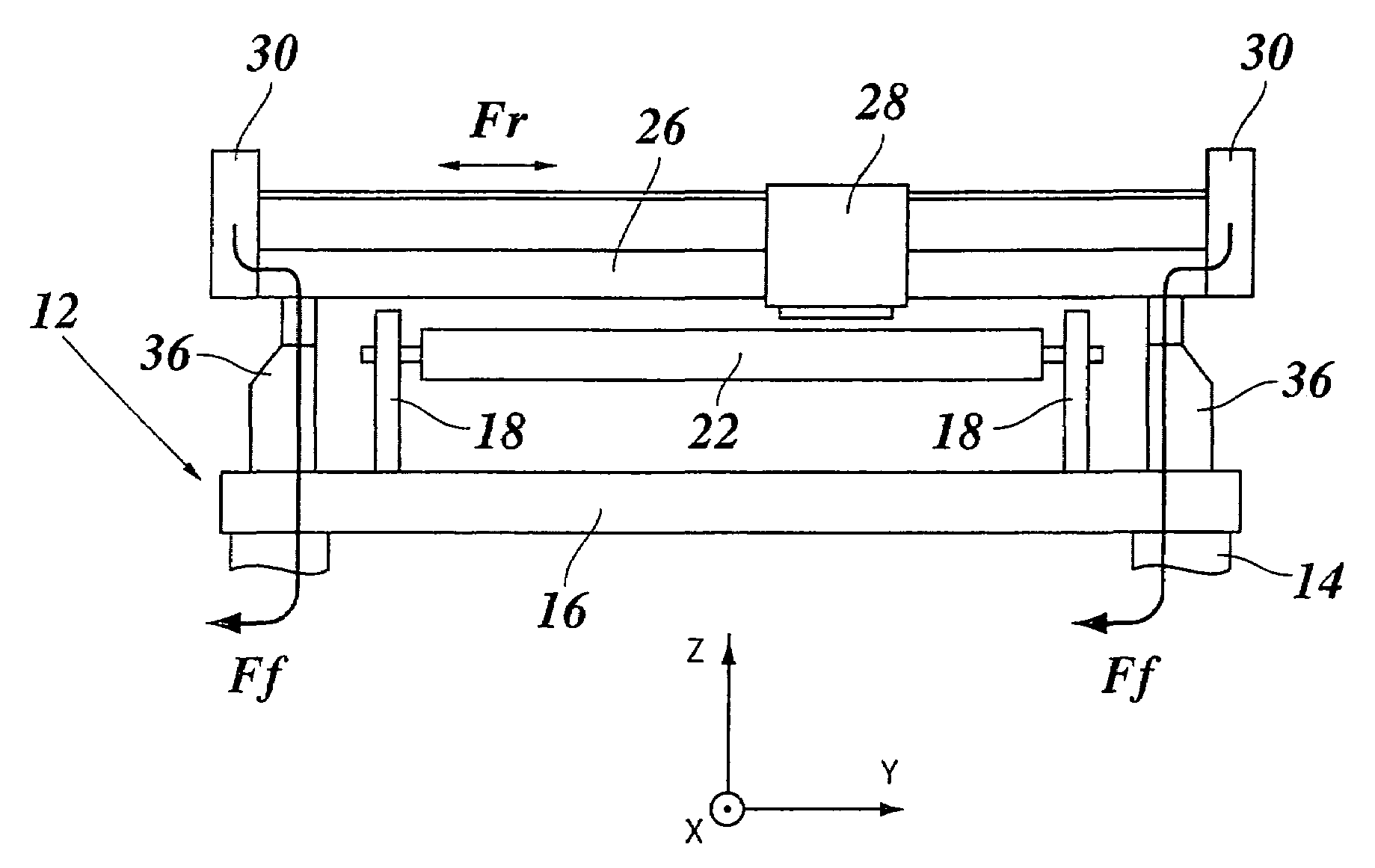
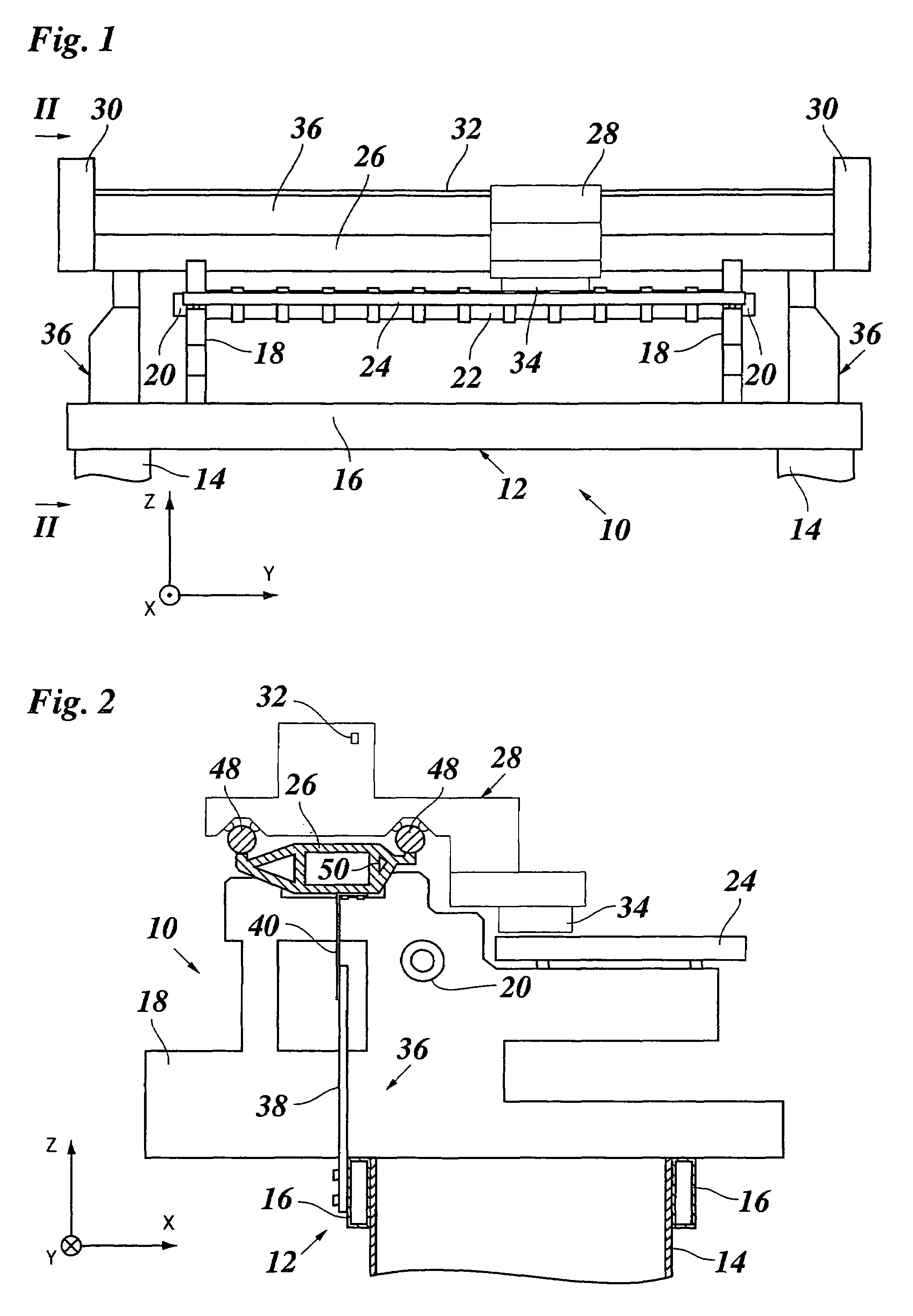
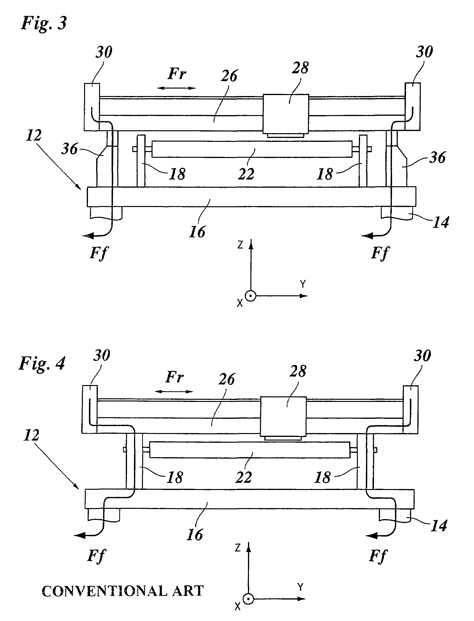
[0012]The printer shown in FIG. 1 includes a frame 10 which is composed of a lower frame 12 formed by two uprights 14 and two cross-bars 16, and an upper frame that is formed by two plate-like frame members 18 projecting upwardly from the cross-bars 16.

[0013]A bearing assembly is formed by two bearings 20 which rotatably support a platen 22 between the two frame members 18. A sheet support plate 24 is horizontally supported on the two frame members 18 and serves to support a sheet of a recording medium (not shown) which is advanced in the X-direction (normal to the plane of the drawing in FIG. 1) by means of the platen 22. A drive mechanism for the platen 22 has not been shown here for simplicity.

[0014]A guide rail 26 rests on the top ends of the frame members 18 and extends in parallel with the axial direction Y of the platen 22. A carriage 28 is guided on the guide rail 26 and is driven to move back and forth along the guide rail by means of a drive mechanism 30 connected to the c...


PUM


Abstract

A printer including: a frame composed of a lower frame and an upper frame supported on the lower frame, a platen rotatably supported in the upper frame for advancing a recording medium, a guide rail extending in parallel with an axial direction (Y) of the platen, a carriage guided at the guide rail and carrying a printhead, and a drive mechanism adapted to drive the carriage reciprocatingly along the guide rail, wherein the drive mechanism is directly supported in said axial direction (Y) by the lower frame.

Description

[0001]This non-provisional application claims priority under 35 U.S.C. § 119(a) on Patent Application No. 04106833.9 filed in Europe on Dec. 22, 2004, which is herein incorporated by reference.BACKGROUND OF THE INVENTION[0002]The present invention relates to a printer including a frame composed of a lower frame and an upper frame supported on the lower frame, a platen rotatably supported in the upper frame for advancing a recording medium, a guide rail extending in parallel with an axial direction of the platen, a carriage guided at the guide rail and carrying a printhead, and a drive mechanism adapted to drive the carriage reciprocatingly along the guide rail.[0003]A typical example of a printer of this type is an ink jet printer having a printhead or printheads adapted to expel droplets of liquid ink onto the recording medium that is advanced over the platen. The timings at which the nozzles of the printhead are energized must be accurately synchronized with the movement of the ca...

Claims


Application Information

Patent Timeline
Patent Type & Authority Patents(United States)
IPC IPC(8): B41J29/02B41J11/00
CPCB41J19/20
Inventor GOEREE, BARRY B.ZWIERS, HENK-JANNOTTELMAN, FRANK J. H.DIRCKS, LUC G. T.VAN DORP, BAS W. J. J. A.
Owner OCE TECH
Why Eureka
Try Eureka