
Electric machine, assembly and associated method

a technology of electric machines and parts, applied in the direction of shaft assembly, rigid support of bearings, mechanical devices, etc., can solve the problems of unacceptable axial preload on bearings, fretting or wear on shafts or housings, fretting and wear can create particles, etc., to achieve the effect of limiting rotational movemen

Active Publication Date: 2016-12-15
REGAL BELOIT AMERICA
View PDF8 Cites 6 Cited by
  • Summary
  • Abstract
  • Description
  • Claims
  • Application Information

AI Technical Summary

Benefits of technology

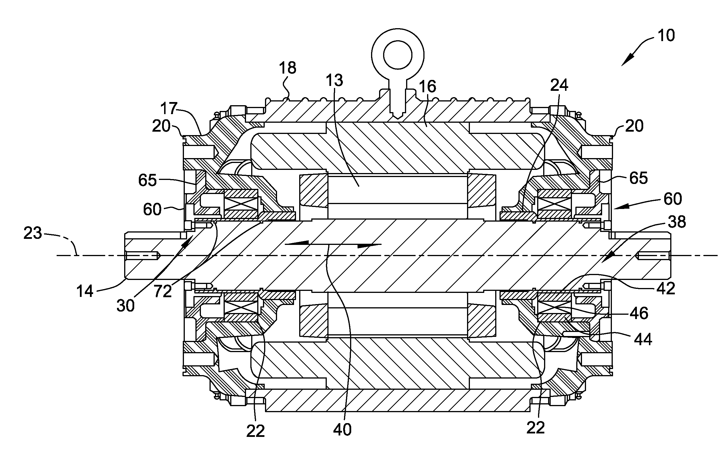
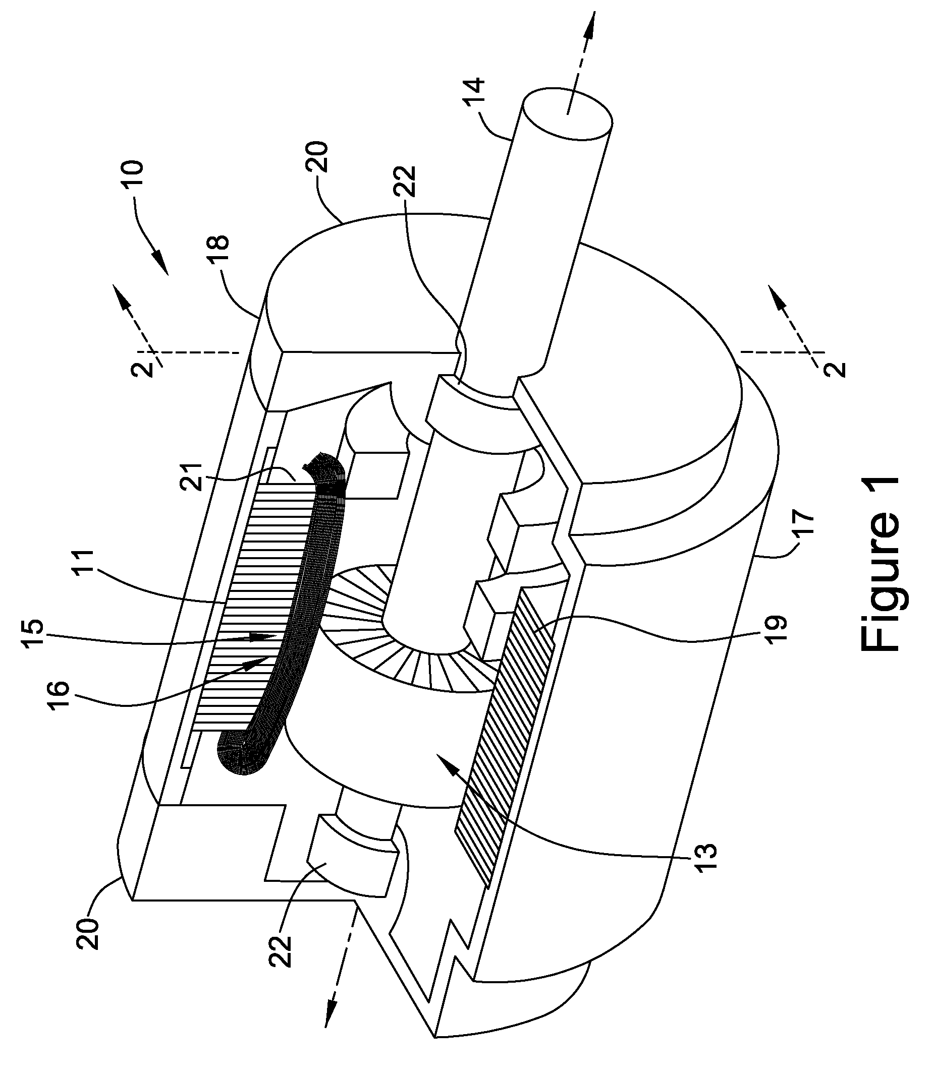
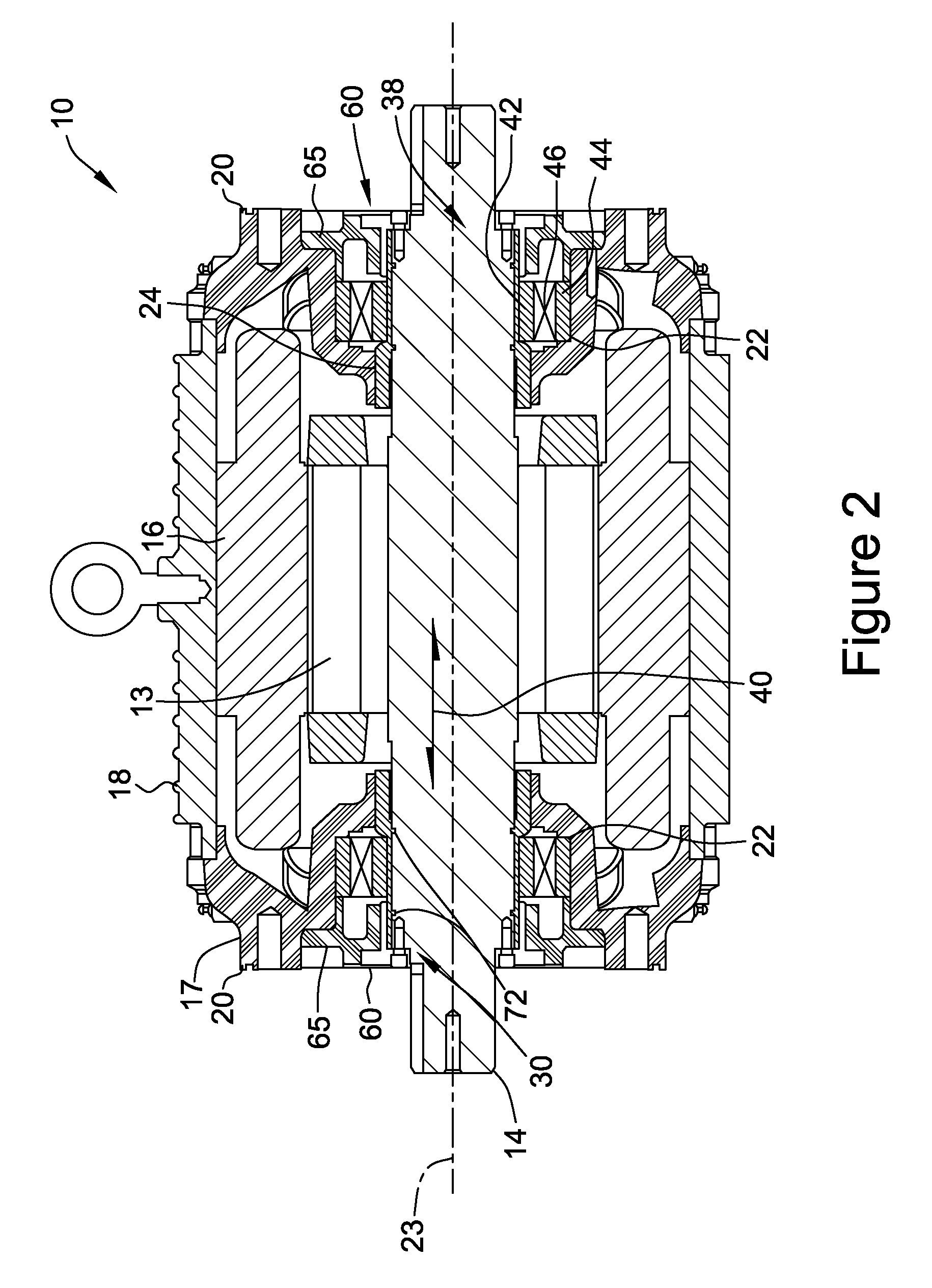
The invention provides an electric machine with a stator and rotor, and a bearing that is fixed to the shaft. The bearing is secured to the sleeve, which is then slidably secured to the shaft. This design allows for limited axial and rotational motion between the sleeve and shaft. The invention also includes a feature that allows for sliding movement between the sleeve and shaft, and a member that limits rotational movement between the sleeve and shaft. The assembly also includes a shaft with circumferential grooves and a sleeve with a void that cooperates with the grooves to allow for limited movement between the sleeve and shaft. The invention also provides a method for securing a bearing to a shaft in an electric machine.

Problems solved by technology

Due to tolerance stacks from manufacturing inaccuracies, thermal expansion of differing materials and assembly inaccuracies, providing interference fits on both races typically results in an unacceptable axial preload on the bearing.
This precession may cause fretting or wear on the shaft or housing.
The fretting and wear can create particles that may migrate through the mechanism.
The particles may propagate into the lubricant and into the bearing rolling elements, leading to shortened bearing life.
Such features, however, add significant costs and provide stress risers to the race and component.

Method used


Image

  • Electric machine, assembly and associated method
  • Electric machine, assembly and associated method
  • Electric machine, assembly and associated method

Examples


Embodiment Construction

[0038]Rotating mechanical mechanisms typically have bearings for supporting the rotating components of the mechanism relative to the stationary components. For rolling element bearings, those having balls, rollers or spherical rollers, typically one element or race is fixed to the rotating component and the other element or race is fixed to the stationary component. The rolling elements provide for motion between one race and the other race.

[0039]Fixing the races to the rotating component and to the stationary component can be accomplished by interference fit of bores to diameter or by forces applied to the faces of the races. Due to tolerance stacks from manufacturing inaccuracies, thermal expansion of differing materials and assembly inaccuracies, providing interference fits on both races of both bearings typically results in an unacceptable axial preload on the bearings.

[0040]For applications where the radial load on the bearing remains in a fixed direction during the mechanism's...


PUM


Abstract

An electric machine is provided. The electric machine includes a stator and a rotor. The rotor is rotatably secured to the stator. The electric machine further includes a shaft secured to the rotor and a sleeve. The sleeve defines a bore and an outer periphery of the sleeve. The sleeve is slidably secured to the shaft. The electric machine further includes a bearing defining a bore of the bearing. At least a portion of the bore of bearing is fixedly secured to at least a portion of the outer periphery of the sleeve.

Description

BACKGROUND OF THE INVENTION[0001]The embodiments described herein relate generally to electric machines, and more specifically, to a mechanism for securing a machine shaft to a bearing.[0002]Rotating mechanical mechanisms typically have bearings for supporting the rotating components of the mechanism relative to the stationary components. For rolling element bearings, those having balls, rollers or spherical rollers, typically one element or race is fixed to the rotating component and the other element or race is fixed to the stationary component. The rolling elements provide for motion between one race and the other race.[0003]Fixing the races to the rotating component and to the stationary component can be accomplished by interference fit of bores to diameter or by forces applied to the faces of the races. Due to tolerance stacks from manufacturing inaccuracies, thermal expansion of differing materials and assembly inaccuracies, providing interference fits on both races typically ...

Claims


Application Information

Patent Timeline
Patent Type & Authority Applications(United States)
IPC IPC(8): H02K5/173H02K5/16H02K15/00F16C35/063
CPCH02K5/1732H02K15/00H02K5/161F16C35/063H02K15/14H02K5/15H02K2213/09F16C2226/62F16C2380/26F16C35/073F16C23/08
Inventor RACZEK, JOHN EDWARDOHRMUNDT, CHRISTOPHER THOMASNELESSEN, JEFFREY PATRICKREAMER, LAURA MICHELLEBARKHOLZ, ALLEN JONATHAN
Owner REGAL BELOIT AMERICA
Learn More