
Mechanical gas bottle dispensing machine

a gas bottle and mechanical technology, applied in the field of mechanical dispensing machines, can solve the problems of complex machines, inability to exchange and return empty bottles, etc., and achieve the effect of preventing the operation of the machin

Inactive Publication Date: 2011-07-12
BORZYM ANDRZEJ
View PDF18 Cites 5 Cited by
  • Summary
  • Abstract
  • Description
  • Claims
  • Application Information

AI Technical Summary

Benefits of technology

[0005]An advantage of the present invention is that the mechanical gas bottle dispensing machine is safe from any hazard since it is entirely mechanical, without using any pneumatic, hydraulic, electric and / or magnetic actuators.
[0006]Another advantage of the present invention is that the mechanical gas bottle dispensing machine allows pick-up of a filled gas bottle with or without the return of an empty bottle, and this without the need of a staff member.
[0007]Still another advantage of the present invention is that the mechanical gas bottle dispensing machine uses different tokens depending on the return of an empty bottle or not.
[0008]Another advantage of the present invention is that the mechanical gas bottle dispensing machine indicates the quantity of filled bottles that remain in the machine, and also prevents operation of the machine when the last filled bottle has been dispensed.
[0009]Yet another advantage of the present invention is that the mechanical gas bottle dispensing machine, when a return empty-gas bottle is to be supplied, functions only if the empty gas bottle is inserted into the machine at the return opening.
[0010]According to an aspect of the present invention, there is provided a mechanical gas bottle dispensing machine comprising mechanical gas bottle dispensing machine for dispensing gas-filled bottles, the machine comprises: a main structure including a slope conveyor for conveying the gas-filled bottles by gravity toward a dispensing opening extending through the main structure adjacent a lower end of the slope conveyor; and a completely mechanical bottle release system, without electric actuators, mounted on the main structure for retaining the gas-filled bottles away from the dispensing opening, the mechanical bottle release system allowing selective release of a lowermost one of the gas-filled bottles adjacent the dispensing opening upon insertion of a token therein.

Problems solved by technology

Some machines are complex and include electrical and / or pneumatic devices for a proper operation, which is known to be hazardous when handling gas bottles, such propane-filled bottles or tanks.
In such case, typically, it is not even possible to make an exchange and return an empty bottle, since they simply do not take empty bottles.

Method used


Image

  • Mechanical gas bottle dispensing machine
  • Mechanical gas bottle dispensing machine
  • Mechanical gas bottle dispensing machine

Examples


Embodiment Construction

[0029]With reference to the annexed drawings the preferred embodiments of the present invention will be herein described for indicative purpose and by no means as of limitation.

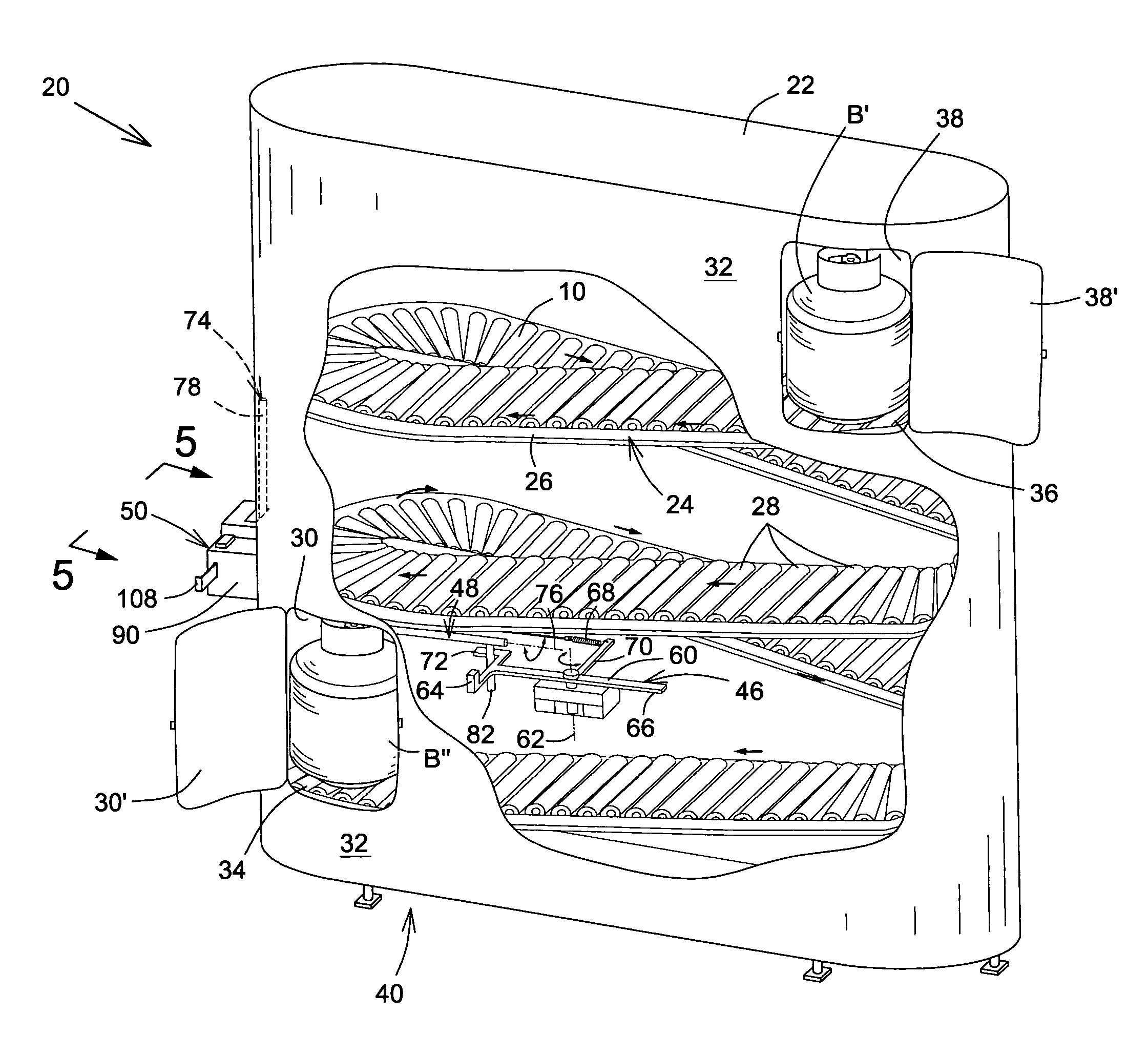
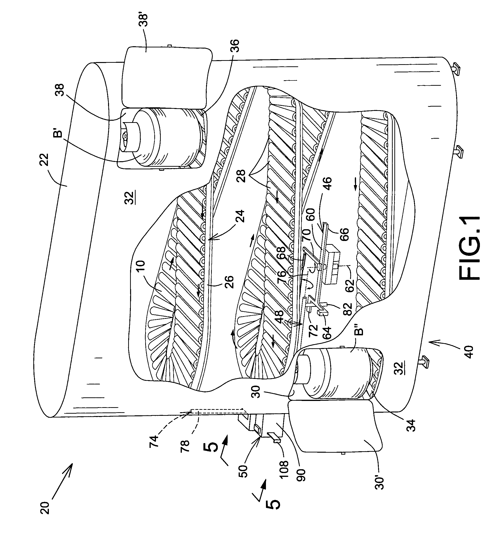
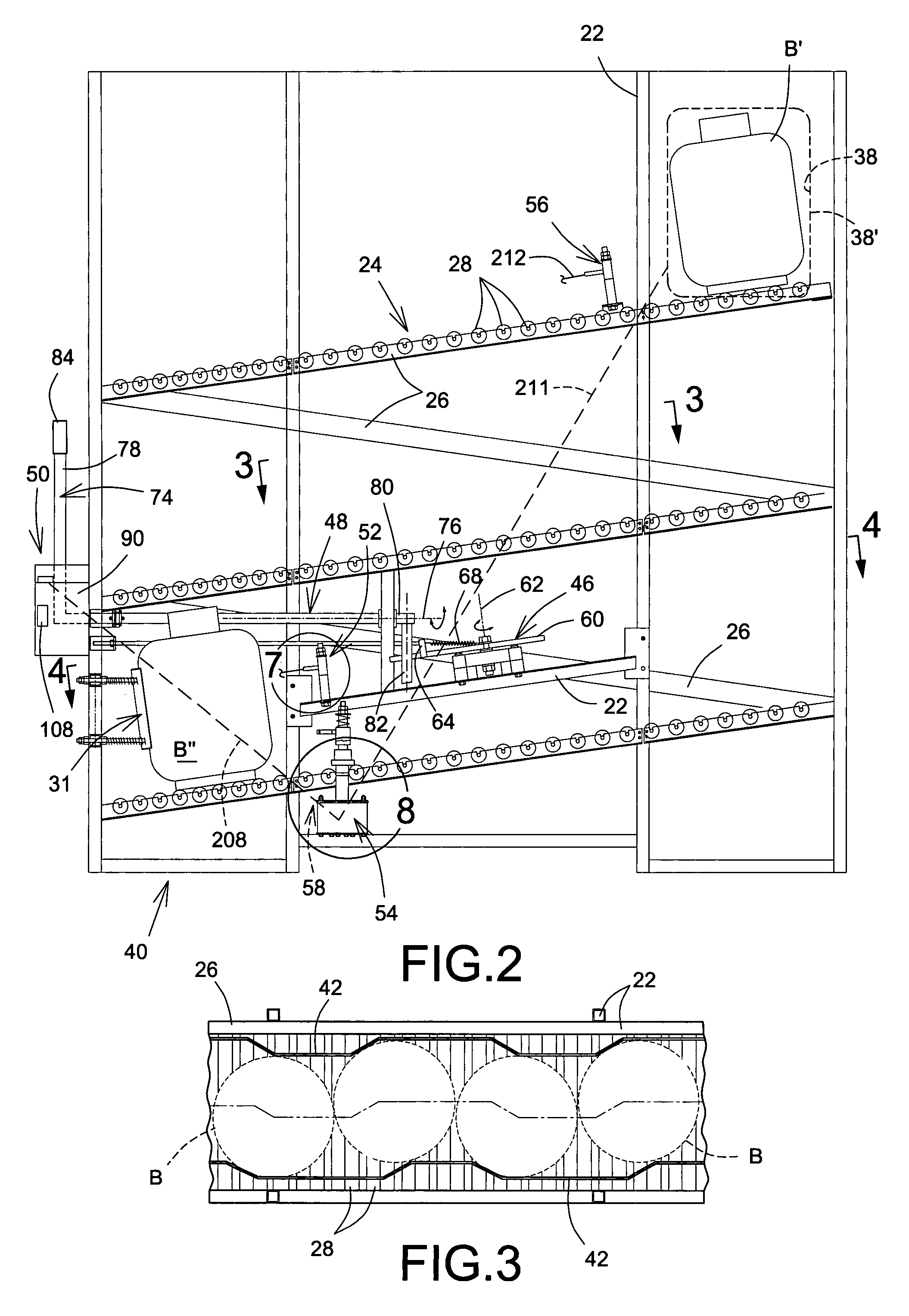
[0030]Reference is now made to FIGS. 1 to 9d, which show a mechanical gas bottle dispensing machine in accordance with an embodiment 20 of the present invention. The entirely mechanical dispensing machine 20 for preferably dispensing gas-filled bottles B such as, but not limited to, propane bottles or tanks or the like, includes a main structure 22 having a slope conveyor 24, preferably made out of a roller conveyor 26 with bearing mounted rollers 28, for conveying the gas-filled bottles B by gravity toward a dispensing opening 30 extending through an external wall 32 of the main structure 22 adjacent a lower end 34 of the slope conveyor 26. An upper end 36 of the conveyor 26 starts adjacent a return opening 38 also extending through the external wall 32 to receive the returned empty bottles B′, when applicab...


PUM


Abstract

An entirely mechanical gas bottle dispensing machine that allows to either only dispense by gravity a filled bottle upon insertion of a first token or dispense a filled bottle with return of an empty bottle upon insertion of a second token.

Description

FIELD OF THE INVENTION[0001]The present invention relates to dispensing machines, and is more particularly concerned with an entirely mechanical dispensing machine for gas bottles such as propane bottles and the like.BACKGROUND OF THE INVENTION[0002]It is well known in the art to have dispensing machines for gas bottles and the like. Some machines are complex and include electrical and / or pneumatic devices for a proper operation, which is known to be hazardous when handling gas bottles, such propane-filled bottles or tanks. To obviate this problem, some machines are simply cages located outside a public store or the like and require a staff member of the store to go out to the gas bottle dispenser, to accompany the client, for opening and closing of the cage. In such case, typically, it is not even possible to make an exchange and return an empty bottle, since they simply do not take empty bottles.[0003]Accordingly, there is a need for an improved entirely mechanical gas bottle disp...

Claims


Application Information

Patent Timeline
Patent Type & Authority Patents(United States)
IPC IPC(8): A47F1/04G07F11/00B65G59/00B65H3/30
CPCA47F1/087G07F7/0609G07F11/34G07F11/36F17C2270/059
Inventor BORZYM, ANDRZEJ
Owner BORZYM ANDRZEJ
Learn More