Piercing terminal pressing clamping device

A piercing terminal and fixture device technology, which is applied in the direction of needle tip/slotted plate contact pieces used to penetrate insulating wires/cable core wires, and can solve the problems of shallow Y-shaped openings, high cost, and inability to fix wires, etc. , to achieve the effect of cost saving, low processing cost and simple operation

Active Publication Date: 2010-01-20
上海元一电子有限公司
View PDF0 Cites 4 Cited by
  • Summary
  • Abstract
  • Description
  • Claims
  • Application Information

AI Technical Summary

Problems solved by technology

Since the shielded wires are scattered wires, the distance between each wire cannot be precisely controlled; and the tooth spacing of the terminal body is 1.27, and the Y-shaped opening is shallow, so the position of the wires cannot be fixed; The wires cannot be exposed on the board, and the top of the wires must withstand the baffle. If loose wires are used, it is difficult to fix them. Therefore, the existing shielding wires for piercing terminals mainly use flat wires, and the loose wires are processed into flat wires. ,higher cost

Method used


Image

  • Piercing terminal pressing clamping device
  • Piercing terminal pressing clamping device
  • Piercing terminal pressing clamping device

Examples


Embodiment Construction

[0032] The present invention will be further described below in conjunction with the accompanying drawings and embodiments.

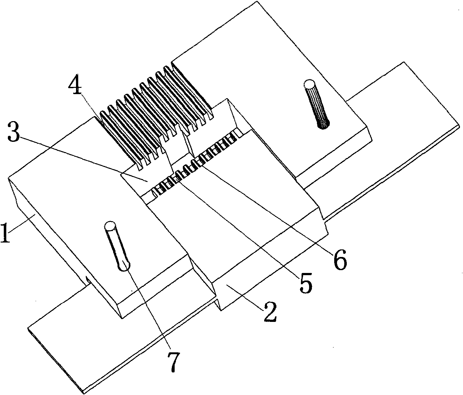
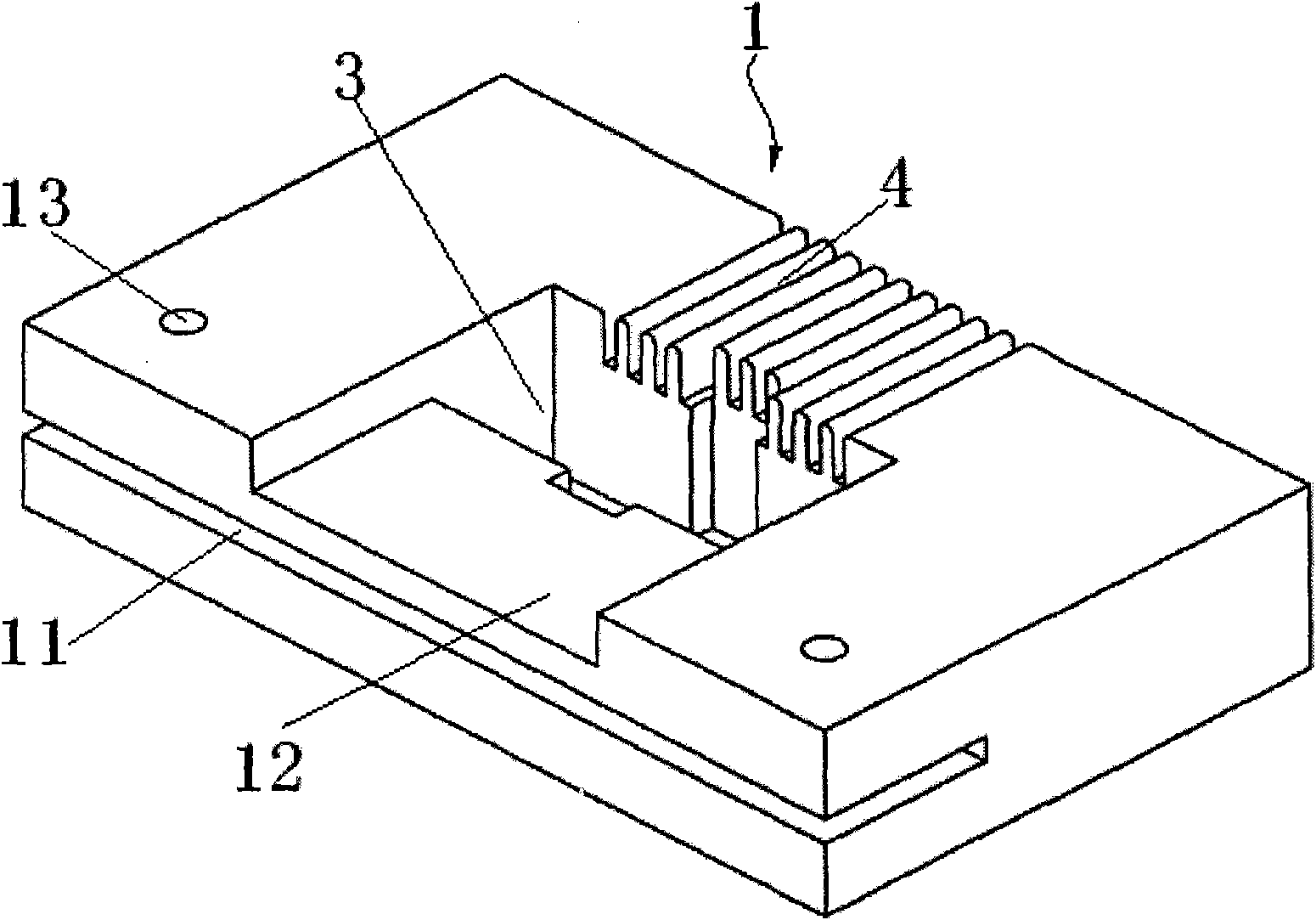
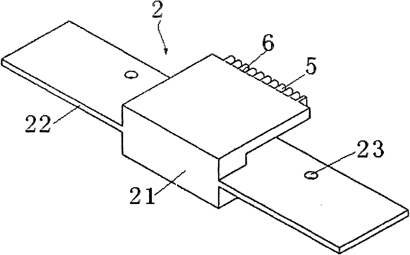
[0033] Such as figure 1 As shown, the puncture-type terminal crimping fixture device of the present invention includes a base 1 and a positioning member 2, the base 1 is provided with a positioning groove 3, and the positioning groove 3 penetrates from the upper surface to the lower surface of the base 1, so The shape of the positioning groove 3 is adapted to the shape of the main body of the terminal. The upper surface of the base on the side where one side wall of the positioning groove 3 is located is provided with a number of main wire slots 4 perpendicular to the positioning slot 3. The width of the main wire slot 4 and the wire diameter Compatible; the positioning part 2 is arranged on the other upper surface of the base relative to the side where the main wire groove is located, and a side end surface of the positioning part 2 is provided with a ...


PUM


Abstract

The invention discloses a piercing terminal pressing clamping device, comprising a base and a positioning piece, wherein, a positioning groove is arranged on the base and penetrates through the base from the upper surface to the lower surface, the shape of the positioning groove adapts to the shape of a terminal body, a plurality of main wire casings which are perpendicular to the positioning groove are arranged on the upper surface of the base on one side on which one side wall of the positioning groove is positioned, and the width of each main wire casing adapts to the diameter of a guide line; the positioning piece is arranged on the other upper surface of the side on which the main wire casings are positioned and to which the base corresponds, one lateral end face of the positioning piece is provided with auxiliary wire casings, each auxiliary wire casing and each main wire casing are opposite to and matched with each other on the same plane, a positioning face is arranged on the end of each auxiliary wire casing, and the positioning groove is positioned between the main wire casings and the auxiliary wire casings. The invention has the advantages of low manufacturing cost and easy and pellucid operation of processing method, and can not cause potential safety hazard to operators, etc.

Description

technical field [0001] The invention belongs to the technical field of fixtures, in particular to a piercing type terminal crimping fixture device for preliminary crimping and positioning of a wire and a piercing type terminal seat. Background technique [0002] Generally speaking, there are three ways to connect the terminals and wires of the connector: welding type, riveting type and piercing type. Since the piercing type connection is usually more convenient to operate, it only needs to be relatively small. Piercing the outer skin of the wire has high efficiency, so it is widely used. The piercing terminal block mainly includes a terminal body and a cover plate with thorns. During the assembly process, the wire needs to be straddled between the terminal body and the cover plate, and then is applied from the side of the cover plate to the side of the terminal body through a special clamp. Press, so that the wire is pierced and assembled with the terminal block. Since the...

Claims


Application Information

Patent Timeline
Patent Type & Authority Applications(China)
IPC IPC(8): H01R4/24
Inventor 郭洁
Owner 上海元一电子有限公司
Why Eureka
Try Eureka