Incandescent lamp and illumination system with optimized filament shape and size

a technology of filament shape and size, which is applied in the direction of incadescent body mounting/support, discharge tube/lamp details, incadescent envelope/vessel, etc., can solve the problems of reducing efficiency, reducing the proportion of light emitted from the center of the inside coiled coil, and reducing the efficiency of light, so as to achieve a higher proportion of light emitted and higher collection efficiency

Inactive Publication Date: 2011-07-12
WIMBERLY RANDAL LEE
View PDF11 Cites 0 Cited by
  • Summary
  • Abstract
  • Description
  • Claims
  • Application Information

AI Technical Summary

Benefits of technology

[0013]The present invention is embodied in an incandescent lamp adapted for use with a concave reflector. Additionally, the lamp filament size can be optimized for use with a specific range of concave reflectors to produce a beam of light with a smooth field of illumination that utilizes a higher proportion of the light emitted by the lamp, i.e., that provides a higher collection efficiency.
[0014]In one embodiment of the invention the incandescent lamp includes a filament that is arranged in coiled coils that have a longitudinal axis that is perpendicular to the reflector longitudinal axis and the larger coils of the coiled coil filament spaced from each other by a distance substantially the same as the coil diameter. This size gap between the coiled coils and the shape of those coils being aligned with the curvature of the reflector surface provides that a higher number of points along the entire length of coil that forms the coiled coil of the filament will incandesce and produce a solid wave front of light that is aligned with the center of said filament.
[0015]If the gap size is smaller than this, as shown in the prior art drawing FIG. 11A, the filament coils will block or absorb a substantial part of the light that is radiated from the center of the inside coiled coils and decrease efficiency. If the gap size is larger than this, as shown in the prior art drawing FIG. 11B, the wave front will include gaps in the center with lower light intensity that will be projected in the beam and appear as shadows or clouding of the beam pattern and, the size of the filament will increase to a point where it will fall outside the focal region and that light will be rendered substantially useless, thereby also decreasing efficiency.

Problems solved by technology

If the gap size is smaller than this, as shown in the prior art drawing FIG. 11A, the filament coils will block or absorb a substantial part of the light that is radiated from the center of the inside coiled coils and decrease efficiency.
If the gap size is larger than this, as shown in the prior art drawing FIG. 11B, the wave front will include gaps in the center with lower light intensity that will be projected in the beam and appear as shadows or clouding of the beam pattern and, the size of the filament will increase to a point where it will fall outside the focal region and that light will be rendered substantially useless, thereby also decreasing efficiency.

Method used


Image

  • Incandescent lamp and illumination system with optimized filament shape and size
  • Incandescent lamp and illumination system with optimized filament shape and size
  • Incandescent lamp and illumination system with optimized filament shape and size

Examples


first embodiment

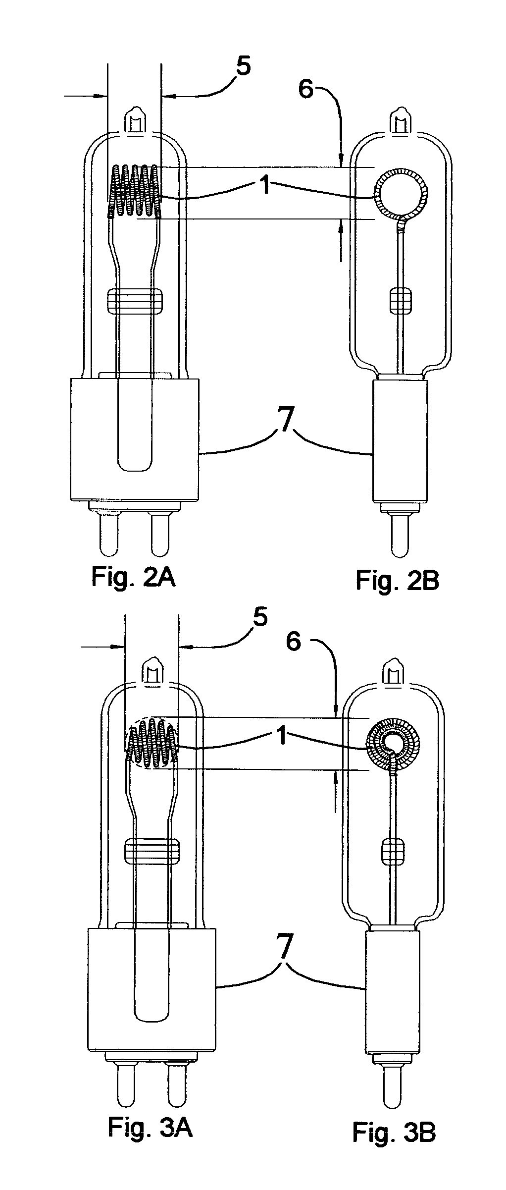
[0035]FIGS. 2A and 2B are front and side views, respectively, of an incandescent lamp constructed in accordance with the invention and used in the incandescent illumination system shown in FIG. 9. This embodiment including a coiled coil filament wherein the larger coiled coils are evenly spaced from each other by a distance selected to be beyond a distance at which arcing between adjacent coiled coils can occur and as close as possible to a distance substantially the same as the coil diameter. Additionally the diameter 5 and height 6 of the filament 1 is a dimension up to the diameter 13 and height 12 dimension of the focal region 21 of said reflector 8.

[0036]When an electrical current is supplied to the filament 1, every segment of the filament will incandesce. Because of the filament's special geometric arrangement, the great majority of the emitted incandescent light is directed toward the concave reflector from a point that the reflector 8 sees as the center of the filament 1 pl...

second embodiment

[0048]FIGS. 3A and 3B are front and side views, respectively, of an incandescent lamp constructed in accordance with the invention and used in the incandescent illumination system shown in FIG. 10. This embodiment including a coiled coil filament wherein the larger coiled coils are evenly spaced from each other by a distance selected to be beyond a distance at which arcing between adjacent coiled coils can occur, as close as possible to a distance substantially the same as their coil diameter, and the diameters of said large coiled coils are of different sizes and arranged so the overall shape of the filament is a sphere. The smaller diameters of the outer large coiled coils reduces blockage of internal light radiation from points along certain adjacent coiled coils of the filament and allows more direct horizontal outward radiation from the side of said filament segments. Additionally the diameter 5 and height 6 of the filament 1 is a dimension up to the diameter 13 and height 12 d...


PUM


Abstract

An incandescent lamp that is specially adapted for use in combination with a concave reflector in providing a high-intensity beam of light. The lamp includes an optimized filament shape that consist of a filament arranged in coiled coils having a longitudinal axis perpendicular to the reflector longitudinal axis and the larger coils of the coiled coil filament spaced from each other by a distance substantially the same as the filament coil diameter. The filament length, width, and height can be limited to substantially twelve millimeters to optimize the lamp for use with concave reflectors having a focal length of substantially twenty five millimeters, any type curvature, and any size diameter.

Description

[0001]REFERENCES CITED:U.S. Pat. No. 6,744,187August, 1940SpaethU.S. Pat. No. 4,686,412April, 1987Johnson, Jr.U.S. Pat. No. 5,268,613Dec. 7, 1993CunninghamU.S. Pat. No. 6,034,473Mar. 7, 2000McBride, Jr., et alU.S. Pat. No. 6,525,452 B1Feb. 25, 2003GuinardU.S. Pat. No. 6,744,187June 2004WimberlyBACKGROUND OF THE INVENTION[0002]This invention relates generally to incandescent illumination systems or fixtures and, more particularly, to incandescent lamps adapted for use in combination with a concave reflector in collecting a high proportion of the emitted light and projecting a high-intensity beam with a smooth and even beam pattern.[0003]Incandescent lamps of this particular kind are useful in theater, television, architectural, and general purpose lighting fixtures that provide high-intensity beams of light. In such fixtures, it is desirable to collect as high a percentage of the emitted light as possible and to redirect that collected light as a high-intensity beam having a desired ...

Claims


Application Information

Patent Timeline
Patent Type & Authority Patents(United States)
IPC IPC(8): H01K1/26H01K1/50
CPCH01K1/14
Inventor WIMBERLY, RANDAL LEE
Owner WIMBERLY RANDAL LEE
Why Eureka
Try Eureka