
Control system and communication system for digital mixer

a control system and communication system technology, applied in the field of control, can solve the problems of increasing production costs, unavoidably increasing the number of devices on the isup>2/sup>c bus, and the bus interface is more complicated than the serial communication interface, so as to reduce production costs, prevent data collision, and simplify the configuration

Inactive Publication Date: 2011-07-12
YAMAHA CORP
View PDF16 Cites 4 Cited by
  • Summary
  • Abstract
  • Description
  • Claims
  • Application Information

AI Technical Summary

Benefits of technology

The solution reduces the number of devices on the primary bus, lowers production costs, and enhances data communication reliability by preventing collisions and eliminating the need for arbitration, while allowing second-class devices to serve as error checkers and efficiently use resources.

Problems solved by technology

Therefore, the number of repeaters for use in an apparatus composed of a plurality of devices is also increased, resulting in increased costs of production.
Specifically, the digital mixer includes more numbers of operators and indicators. than those of the electronic musical instruments, such that it has a disadvantage in that it must unavoidably increase the number of devices on the I2C bus.
For example, the bus interface is more complicated than a serial communication interface such as an RS232C.

Method used


Image

  • Control system and communication system for digital mixer
  • Control system and communication system for digital mixer
  • Control system and communication system for digital mixer

Examples


Embodiment Construction

1. Hardware Configuration of Embodiment

1.1 Operation Panel (100) Configuration

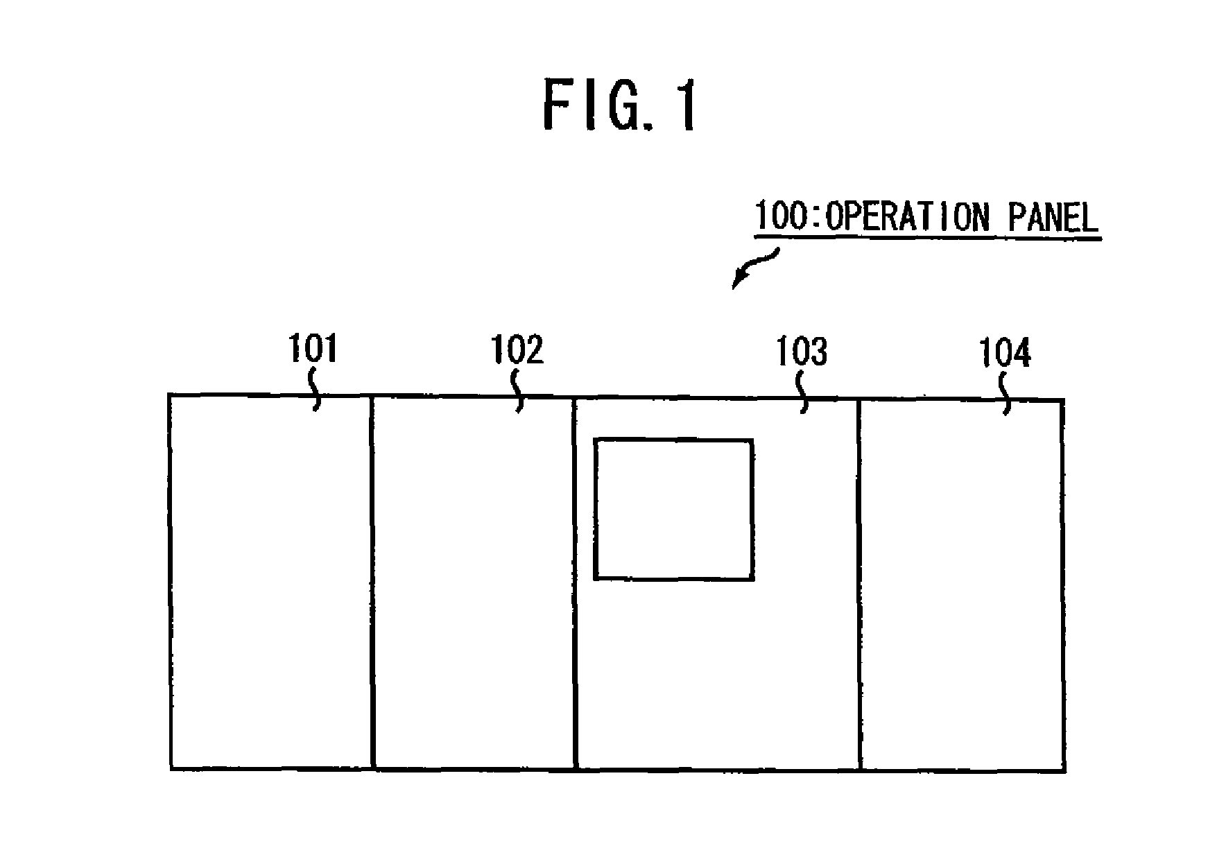
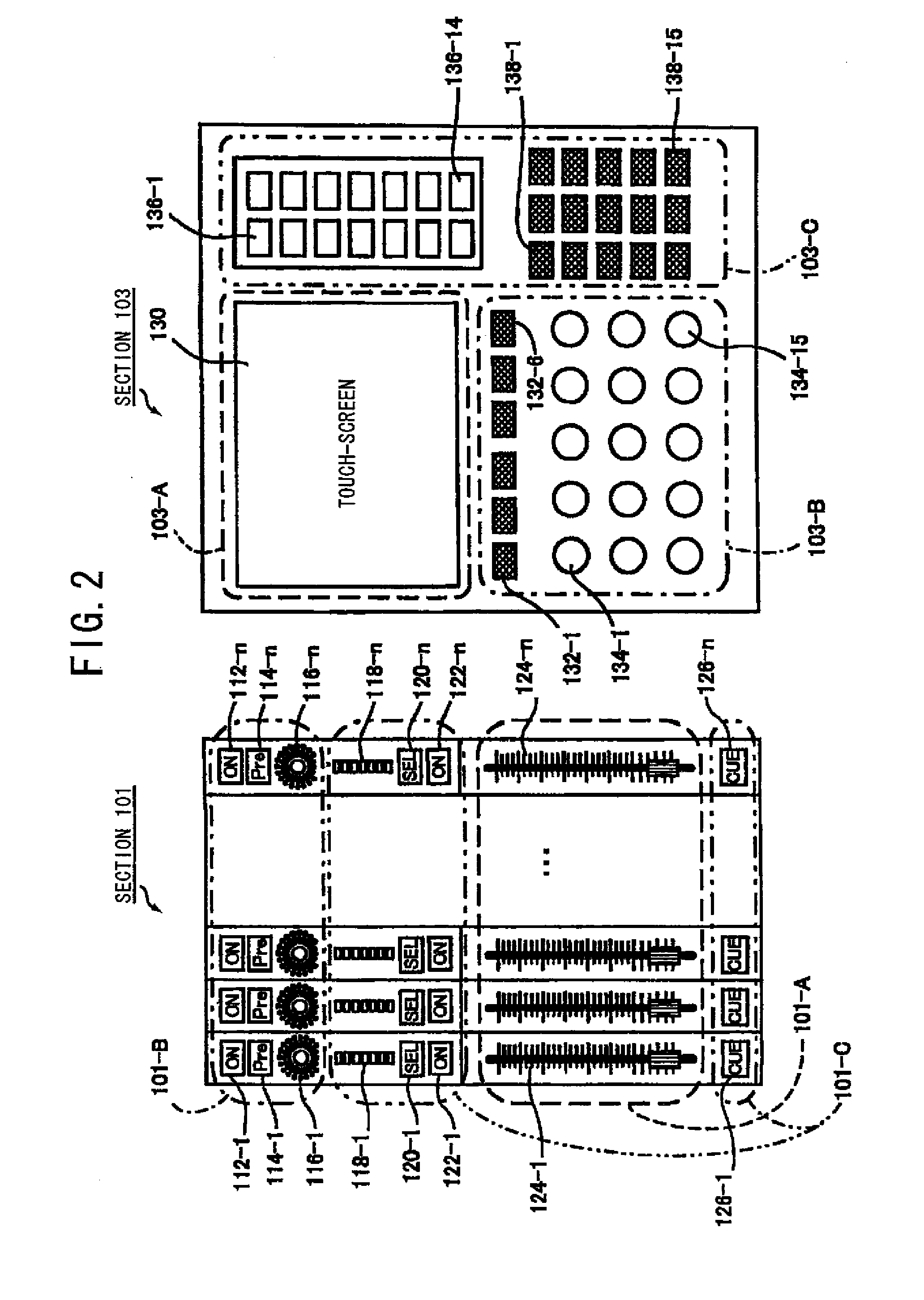
[0041]The operation panel (100) for use in the digital mixer according to a preferred embodiment of the present invention will hereinafter be described with reference to FIG. 1. The operation panel 100 is composed of four sectors (i.e., sections 101˜104). Each of the sections 101 and 102 includes a fader (or the like) for adjusting the volume of an input channel. Likewise, the section 104 includes a fader (or the like) for adjusting the volume of an output channel. The section 103 is adapted to establish detailed parameters for use in a single channel selected from among I / O channels. An audio signal equipped with adjusted volume- and sound quality-levels in individual input channels is outputted to a plurality of buses (i.e., a stereo bus, a MIX bus, and a CUE bus, etc.).

[0042]In this case, the stereo bus is indicative of a bus for mixing an audio signal capable of absorbing sound at guest seats. The MIX ...


PUM


Abstract

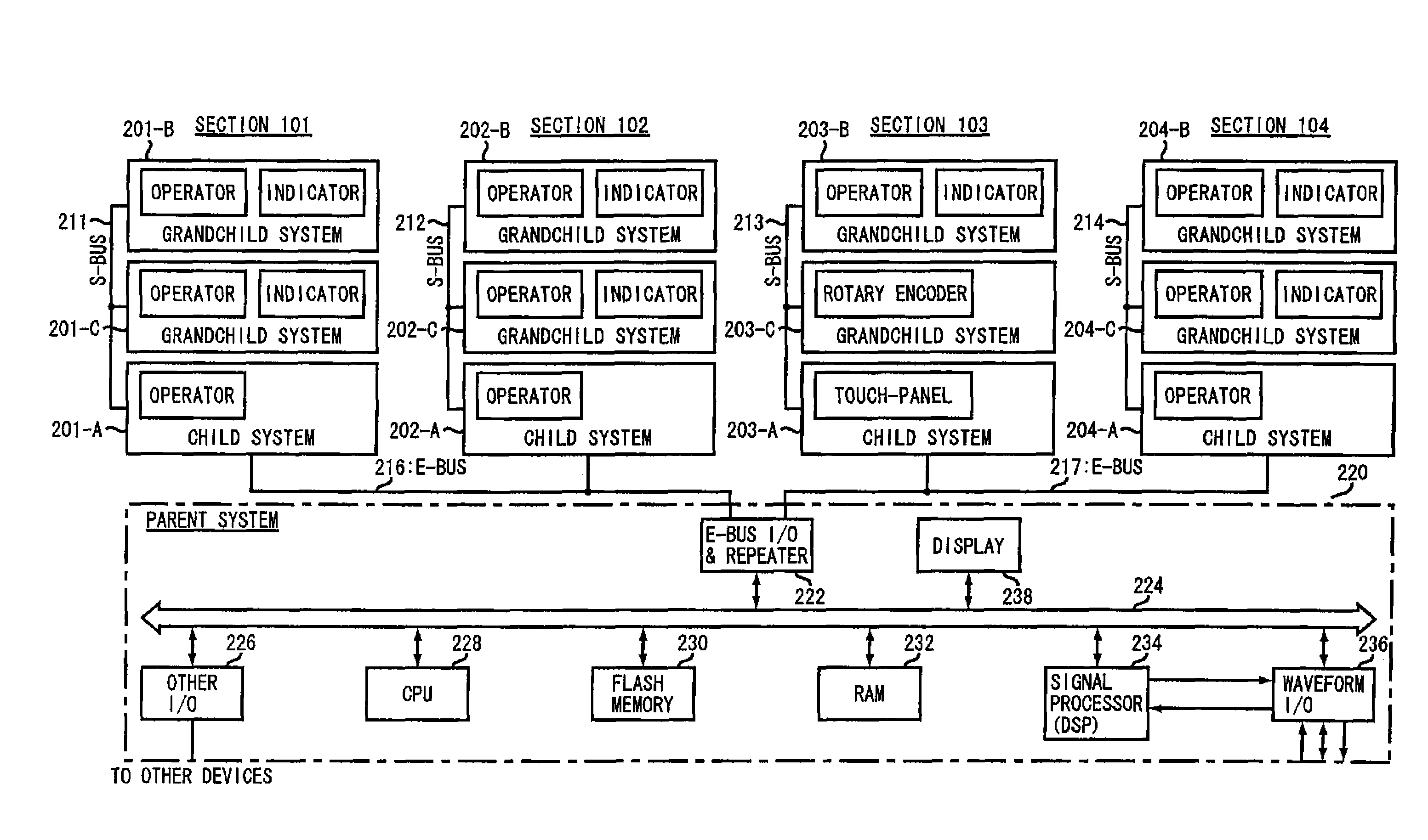
In a control system of a digital mixer, first class devices are connected via a first class bus, and second class devices are connected to each first class device via a second class bus. The number of first class devices, which require a specific function for adding source and destination addresses to data, can be reduced by the number of the second class devices. Moreover, the second class device which does not require the specific function for adding source and destination addresses to data input / output operations is cheaper than the first class device, resulting in the implementation of simplified configuration and reduced production costs.

Description

CROSS-REFERENCE TO RELATED APPLICATIONS[0001]This application is a continuation of U.S. patent application Ser. No. 11 / 377,126, filed Mar. 15, 2006, the entire disclosure of which is incorporated herein by reference.BACKGROUND OF THE INVENTION[0002]1. Technical Field of the Invention[0003]The present invention relates to a control system and a communication system capable of being properly used to control a digital mixer or the like.[0004]2. Description of the Related Art[0005]Conventionally, a serial bus (i.e., an I2C bus) for enabling a plurality of devices to communicate with each other via two signal lines has been well known to those skilled in the art. A specific bus (i.e., an E-bus) formed by applying the I2C bus to data communication between internal devices (e.g., a keyboard, a panel operator, an indicator, and a sound source, etc.) contained in an electronic musical instrument has been disclosed in Japanese Patent Laid-open Publication No. 2002-251183 and corresponding U.S...

Claims


Application Information

Patent Timeline
Patent Type & Authority Patents(United States)
IPC IPC(8): G06F3/00G10H1/18
CPCG06F13/4291H04H60/04
Inventor HOTTA, HARUMICHIKUDO, MASAKIAISO, MASARU
Owner YAMAHA CORP
Learn More