Structural column with footing stilt

a structure column and stilt technology, applied in the direction of machine supports, other domestic objects, mechanical equipment, etc., can solve the problems of increasing the overall project cost, extending the construction phase, and affecting the construction effect of the structur

Active Publication Date: 2011-07-19
MORTON BUILDINGS
View PDF67 Cites 27 Cited by
  • Summary
  • Abstract
  • Description
  • Claims
  • Application Information

AI Technical Summary

Benefits of technology

[0017]Thus, the subject invention as defined by these later expressions of the invention are effective to resist inadvertent shifting of the column assembly out of its predetermined orientation during the concrete pouring step. Therefore, a column assembly made in accordance with this aspect of the invention is more likely to remain in its preferred orientation and location even if the construction workers are not particularly careful or if they do not properly set temporary brace structures prior to the step of pouring the concrete in the hole.

Problems solved by technology

These multiple trips to the job site increase the overall project cost, as well as extend the duration of the construction phase.
Another issue commonly encountered in the erection of structural column assemblies is the issue of uplift.
It is not always desirable to see or otherwise be required to work around exposed fasteners.
In addition to these prior art examples which include fastening arrangements exposed above the earthen hole, they all include another deficiency.
More particularly, when forming a concrete footing in situ in an earthen hole, the viscous, heavy concrete is likely to urge the bottom end of the post out of the preferred orientation.
If the external, temporary bracing is not sufficiently strong, the poured concrete can cause the column assembly to shift in its earthen hole, resulting in a mis-set shifted orientation in the permanent, cured state.
Because construction workers who are employed during this phase of a construction project are typically under time pressures and may not be disposed to correct for shifting during the pour, this situation can result in serious errors.

Method used


Image

  • Structural column with footing stilt
  • Structural column with footing stilt
  • Structural column with footing stilt

Examples


Embodiment Construction

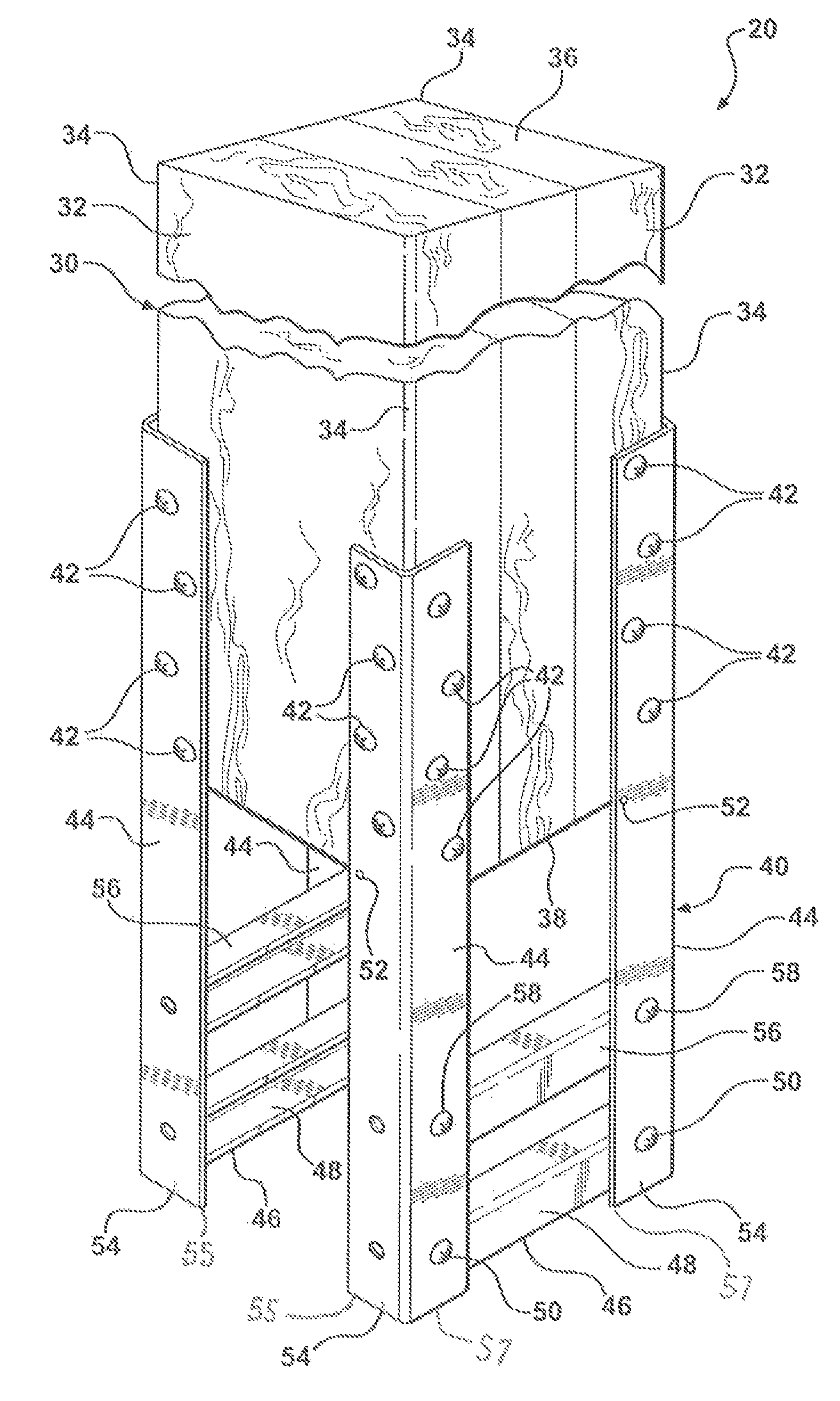
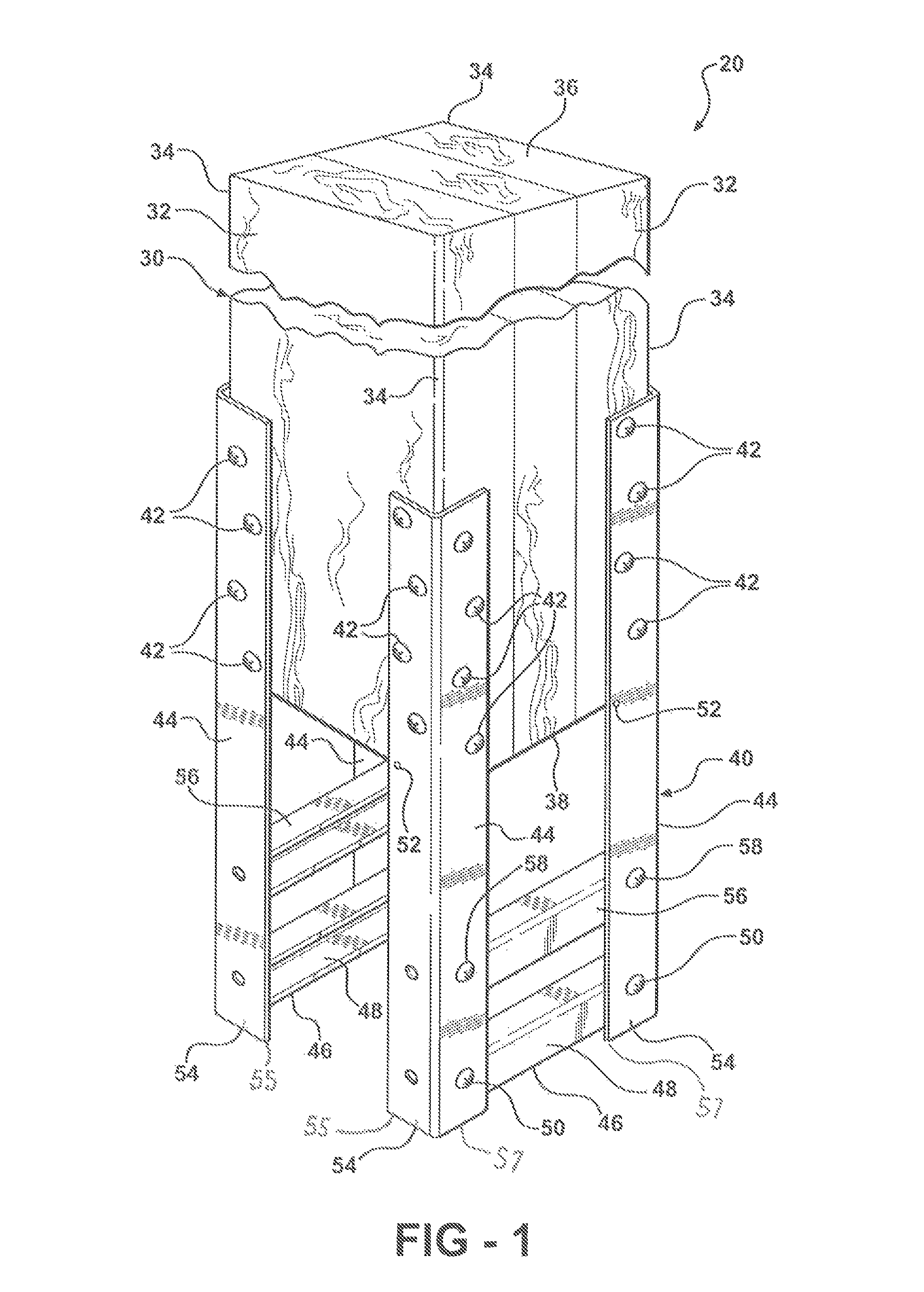
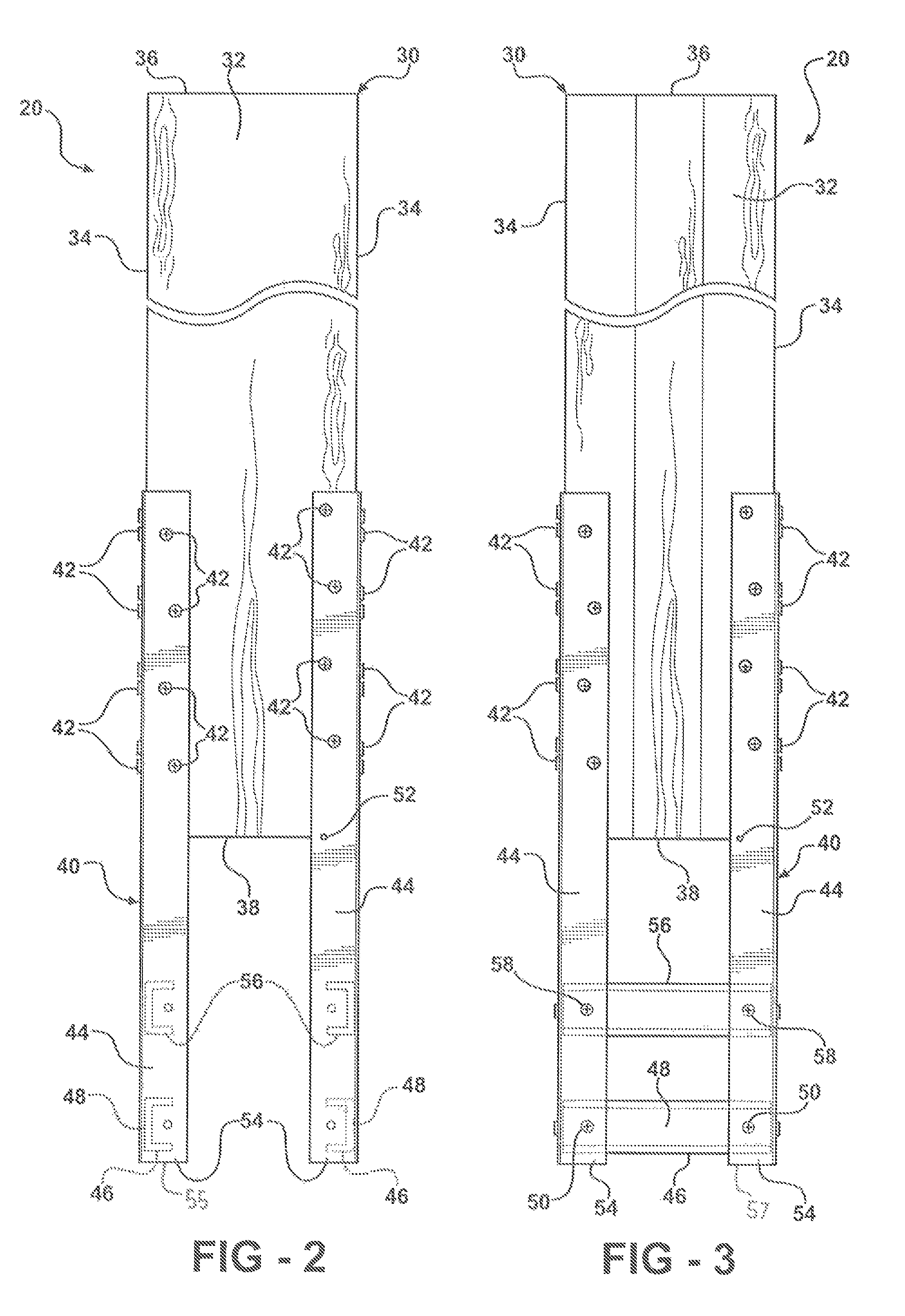
[0031]Referring to the Figures, wherein like numerals indicate like or corresponding parts throughout several views, a structural column assembly according to the subject invention is generally shown at 20 in FIG. 1-4D. The column assembly 20 is of the type adapted to be embedded in a concrete footing, generally indicated at 22 in FIGS. 4B-4D. The concrete footing 22, in turn, is preferably not of the pre-cast type, but rather of that type formed in situ in an earthen hole 24. The hole 24 is formed by any of the known techniques, including digging or boring to a depth which is prescribed by local building codes or customs. The depth can be measured longitudinally from the surrounding grade surface 26 to a floor 28 of the hole 24. Typically, the hole 24 will be cylindrical in form, but other shapes are possible. And, while the preferred implementation of the subject column assembly 20 contemplates forming the hole 24 in the earth per se, it must be appreciated that foreseeable circum...


PUM


Abstract

A structural column assembly of the type used for erecting building structures and the like is bedded in a concrete footing formed in situ in an earthen hole. The column assembly includes a post whose bottom end is suspended above a floor of the hole by a stilt. The stilt includes a plurality of legs which extend from the post's bottom end and grip the hole floor through a plurality of cleats. The cleats help stabilize the column assembly during the concrete pour operation so that it does not shift out of position. The stilt legs are provided with a base pad, which is set below the bottom end of the post at a predetermined distance so that the concrete footing can be poured in a single operation immediately after the hole is formed. The stilt can accommodate posts made from wood, pre-cast concrete or any other known construction material. The stilts can be manufactured from formed flat steel or commercially available angle iron and channel stock.

Description

CROSS-REFERENCE TO RELATED APPLICATIONS[0001]This application claims priority to U.S. Provisional Application No. 60 / 667,161 filed Mar. 31, 2005.BACKGROUND OF THE INVENTION[0002]1. Field of the Invention[0003]The invention relates generally to a structural column assembly such as used to support framing members in the construction of buildings, structures and the like; and more particularly toward a column assembly including a footing stilt for supporting the bottom end of a column post a predetermined distance above the floor of an earthen hole to facilitate the in situ formation of a concrete footing.[0004]2. Related Art[0005]Structural column assemblies of the type used for post-frame construction and pole frame structures typically include an elongated wooden post having a bottom end anchored in the earth and a top, free standing end fixed in an upright position upon which framing, truss or other structural elements are attached. The bottom end of the post is typically supported...

Claims


Application Information

Patent Timeline
Patent Type & Authority Patents(United States)
IPC IPC(8): E02D27/00
CPCE04C3/30
Inventor FEHR, DAVEKNEPP, WAYNE AREMMELE, PAUL
Owner MORTON BUILDINGS
Why Eureka
Try Eureka