Microfluidic valve, method of manufacturing the same, and microfluidic device comprising the microfluidic valve

a microfluidic valve and microfluidic technology, which is applied in the direction of valve operating means/releasing devices, transportation and packaging, etc., can solve the problems of long heating time, difficult to precisely control the opening time of channels, and difficult to miniaturize or integrate biochemical reaction substrates. achieve the effect of rapid and accurate operation

Active Publication Date: 2011-07-19
PRECISIONBIOSENSOR INC
View PDF8 Cites 20 Cited by
  • Summary
  • Abstract
  • Description
  • Claims
  • Application Information

AI Technical Summary

Benefits of technology

[0009]The present invention provides a microfluidic valve that rapidly and accurately performs the operation of controlling flow of a fluid through structures in a platform by application of an external electromagnetic wave energy source and a microfluidic device including the same.
[0010]The present invention also provides a method of manufacturing the microfluidic valve with increased reliability and efficiency. In particular, the present invention provides a method of manufacturing the microfluidic valve, in which processes of manufacturing the microfluidic valve have minimal influence on other constituent elements when a microfluidic device that includes the microfluidic valve is manufactured.
[0018]As a first method of increasing the reliability of combining the upper substrate and the lower substrate, the operation of (a) may comprise a lower substrate that further comprises a protruding pattern formed along the outer walls of the three-dimensional structure, and an upper substrate that at least covers a region that comprises the three-dimensional structure and the protruding pattern, and the operation of (c) may comprise combining the lower substrate by covering it with the upper substrate after an adhesive is coated on a surface of the protruding pattern of the lower substrate.
[0019]As a second method of increasing the reliability of combining the upper substrate and the lower substrate, the operation (a) may comprise preparing a lower substrate that comprises a protruding pattern formed along the outer walls of the three-dimensional structure and an upper substrate that at least covers a region that covers the three-dimensional structure and the protruding pattern, and the operation of (c) may comprise coupling the lower substrate by covering with the upper substrate after coating an adhesive on the upper substrate in a shape corresponding to the shape of the protruding pattern.

Problems solved by technology

However, the valve included in the above substrate requires a large amount of paraffin wax in order to close minute channels, and a large heating element must be included to melt the large amount of paraffin wax.
Thus, it is difficult to miniaturize or integrate the biochemical reaction substrate.
Also, a long heating time is required to melt the paraffin wax and it is difficult to precisely control the opening time of channels.

Method used


Image

  • Microfluidic valve, method of manufacturing the same, and microfluidic device comprising the microfluidic valve
  • Microfluidic valve, method of manufacturing the same, and microfluidic device comprising the microfluidic valve
  • Microfluidic valve, method of manufacturing the same, and microfluidic device comprising the microfluidic valve

Examples


Embodiment Construction

[0025]The above and other aspects of the present invention will become more apparent by describing in detail exemplary embodiments thereof with reference to the attached drawings, in which:

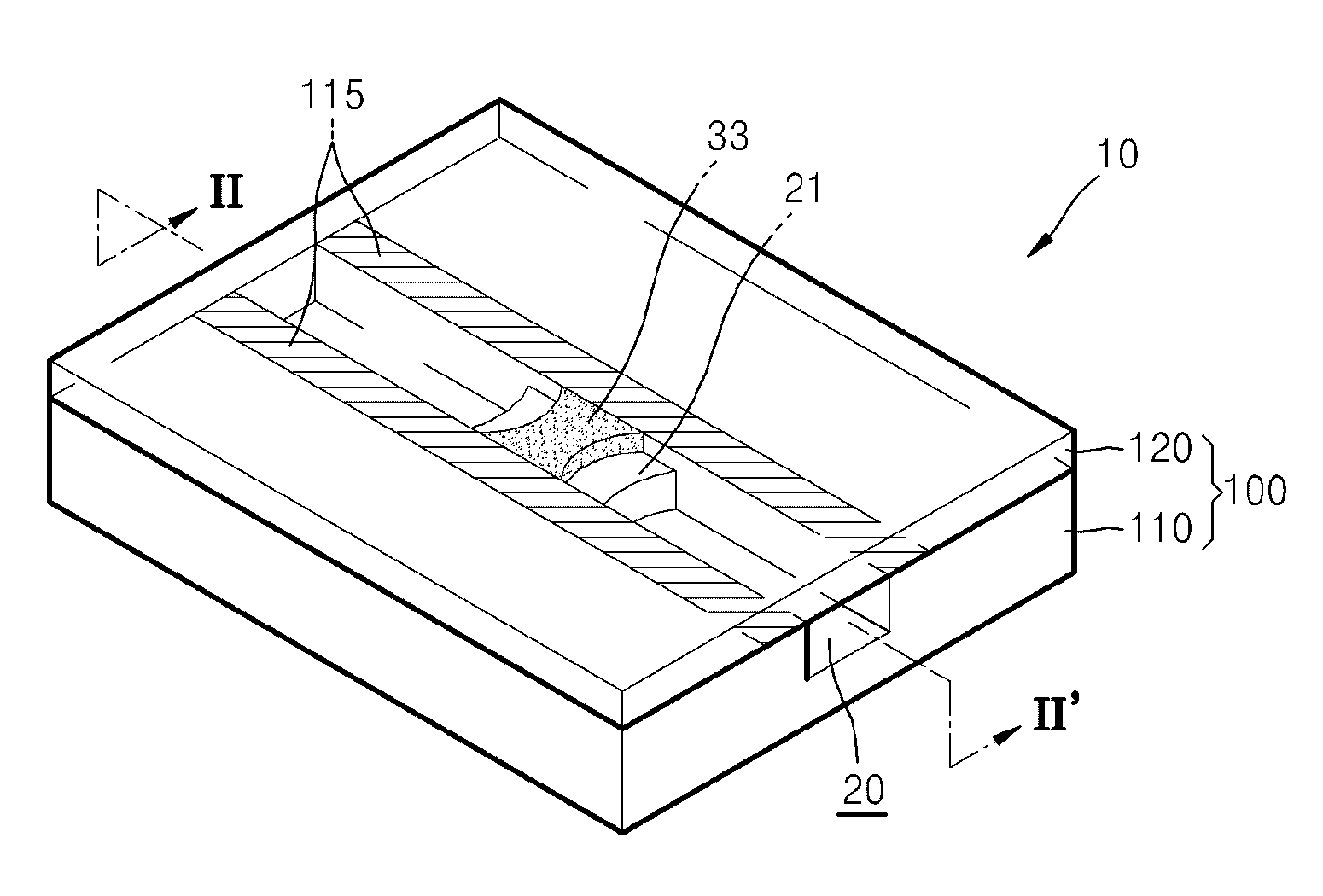
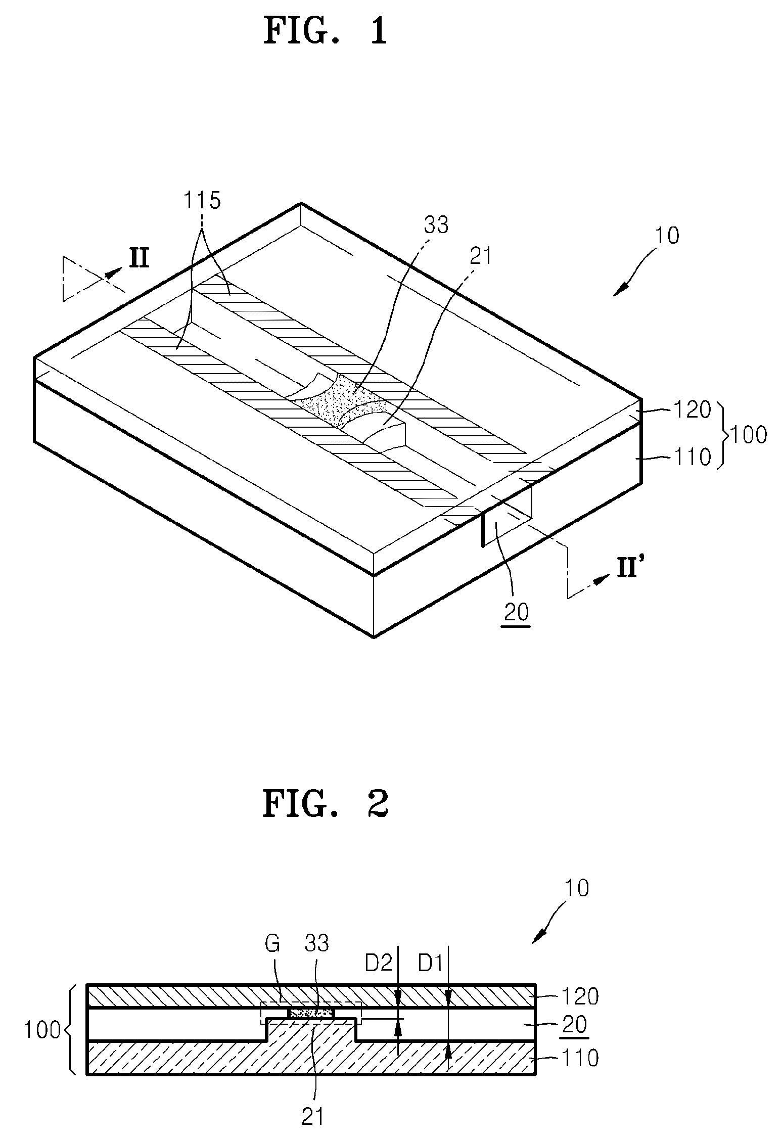
[0026]FIG. 1 is a perspective view of a microfluidic valve according to an exemplary embodiment of the present invention;

[0027]FIG. 2 is a cross-sectional view taken along line II-II′ of the microfluidic valve of FIG. 1, according to an exemplary embodiment of the present invention;

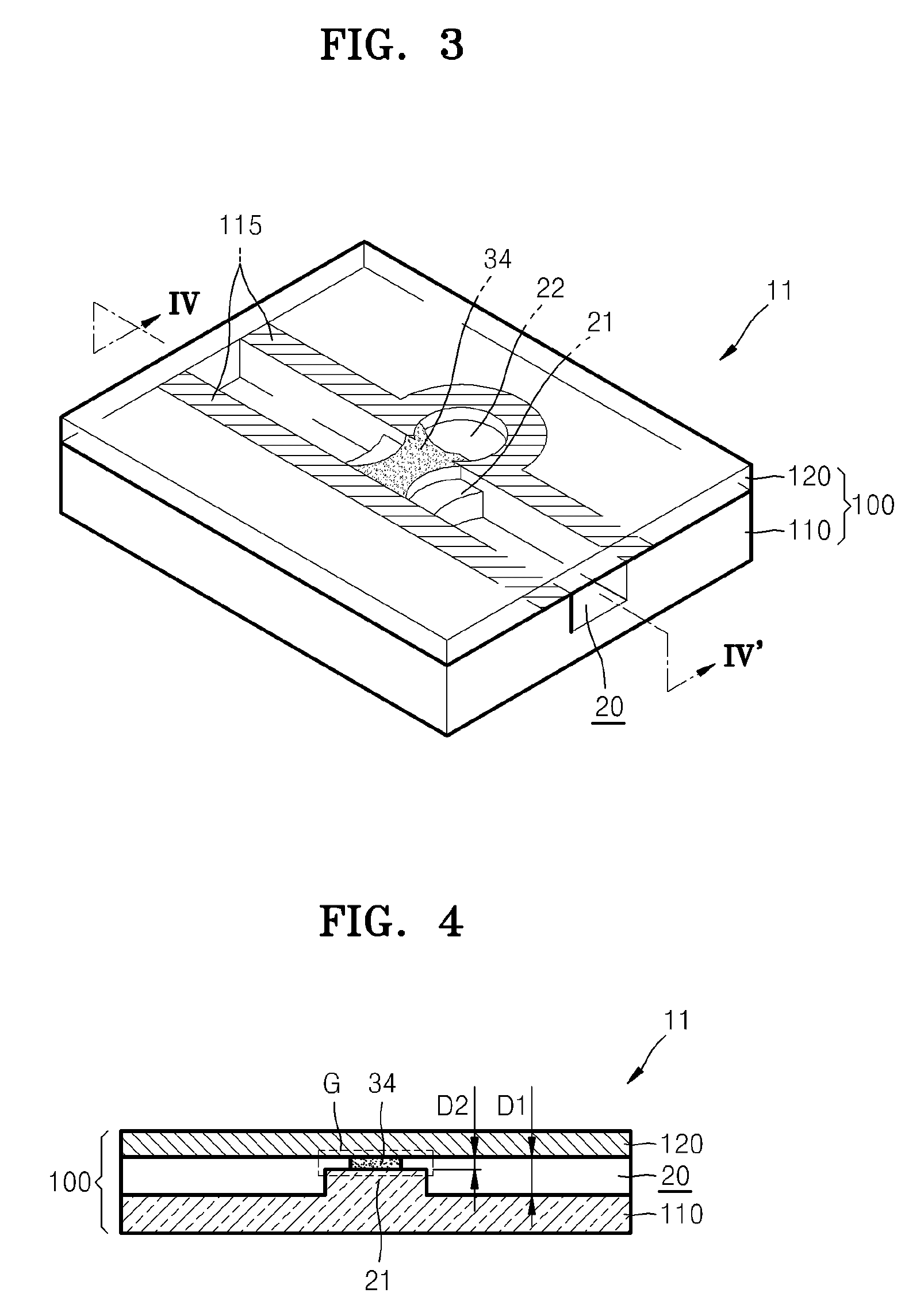
[0028]FIG. 3 is a perspective view of a microfluidic valve according to another embodiment of the present invention according to another exemplary embodiment of the present invention;

[0029]FIG. 4 is a cross-sectional view taken along line IV-IV′ of the microfluidic valve of FIG. 3, according to another exemplary embodiment of the present invention;

[0030]FIGS. 5A through 5C are perspective views illustrating a method of manufacturing the microfluidic valve of FIG. 1, according to an exemplary embodiment of the present in...


PUM

PropertyMeasurementUnit
depth D2aaaaaaaaaa
depth D2aaaaaaaaaa
diameteraaaaaaaaaa

Abstract

Provided is a microfluidic valve, a method of manufacturing the microfluidic valve, and a microfluidic device that employs the microfluidic valve. The microfluidic valve includes a platform that includes two substrates combined facing each other; a channel having a first depth allowing a fluid to flow between the two substrates; a valve gap that is disposed on at least a region of the channel and has a second depth which is smaller than the first depth; and a valve plug that is disposed to fill the valve gap and is formed of a valve material made by mixing a phase change material, which is solid at room temperature, with a plurality of exothermic particles that emit an amount of heat sufficient to melt the phase change material by absorbing electromagnetic waves.

Description

CROSS-REFERENCE TO RELATED PATENT APPLICATIONS[0001]This application claims priority from Korean Patent Application Nos. 10-2007-0061128, filed on Jun. 21, 2007 and 10-2007-0079175, filed on Aug. 7, 2007, in the Korean Intellectual Property Office, the disclosures of which are incorporated herein in their entireties by reference.BACKGROUND OF THE INVENTION[0002]1. Field of the Invention[0003]Apparatuses and methods consistent with the present invention relate to a microfluidic valve, and more particularly, to a microfluidic valve for controlling flow of a fluid through structures in a platform, a method of manufacturing the microfluidic valve, and a microfluidic device including the microfluidic valve.[0004]2. Description of the Related Art[0005]Devices that perform a biological or chemical reaction by manipulating a small volume of a fluid are referred to as microfluidic devices. A microfluidic device includes microfluidic structures disposed in a platform, wherein the platform can...

Claims


Application Information

Patent Timeline
Patent Type & Authority Patents(United States)
IPC IPC(8): F15C1/04
CPCF16K99/0001F16K99/0032F16K99/004Y10T29/49412F16K2099/0084Y10T137/2191Y10T137/2196
Inventor PARK, JONG-MYEONCHO, YOON-KYOUNGLEE, BEOM-SEOKLEE, JEONG-GUN
Owner PRECISIONBIOSENSOR INC
Why Eureka
Try Eureka