Zeroing system of a rolling stand

a technology of zeroing system and rolling stand, which is applied in the direction of metal rolling arrangement, measuring device, manufacturing tool, etc., can solve the problems of strip portions, difficult to control difficulty in adjusting the thickness of the roll,

Active Publication Date: 2015-09-08
DANIELI & C OFF MEC SPA
View PDF5 Cites 1 Cited by
  • Summary
  • Abstract
  • Description
  • Claims
  • Application Information

AI Technical Summary

Benefits of technology

[0007]It is a main object of the present invention to make a zeroing system of a rolling stand which allows one to replace the working and / or supporting cylinders or rolls in a four-high rolling stand for hot rolling strips and to subsequently zero the rolling stand without removing or stopping the strip between the rolls themselves.
[0008]A further object of the invention is to make a zeroing system of a rolling stand which further allows one to very rapidly and accurately carry out the zeroing operation, allowing one to increase productivity in the entire plant.
[0027]possibility of zeroing the rolling stand by means of contact of the working rolls without in all cases removing the strip from between the rolls themselves. This allows one to not interrupt the rolling process with the nearby rolling stands but simply to bypass the rolling stand concerned by the roll change, and in particular to not interrupt the casting process in case of endless rolling;
[0030]Preferably, but not necessarily, working rolls are changed one rolling stand at a time. While the working rolls are being changed, the respective rolling stand, which is provided with, in all cases, an auxiliary roll system to maintain the material pass-line at a constant condition, is dummy, and the rolling process continues with one less active rolling stand, in all cases for a very short time.
[0031]By extracting the working rolls of a rolling stand, both the transient of the thickness change between rolling stands and the loop of the strip between the previous rolling stand and the next one can be easily managed.
[0032]In a conventional coil-to-coil process, if production is carried out in the rolling mill only, the solution according to the invention allows an increase in productivity.

Problems solved by technology

In rolling plants, the working and / or supporting rolls of the rolling stands must be periodically replaced due to wear.
Both methods have some disadvantages: the first method does not allow one to take into account the clearance between mechanical parts (e.g., bearings, adjustment screws etc.) in the zeroing process, and the second method causes strip portions, the thickness of which may be out of tolerance.
In the case of Hot Strip Mills (HSM), this operation is more complex because the hot strip cannot be stopped, because of the absence of loppers and because of the risk of damaging the working rolls caused by local temperature increase of the same rolls in contact with the high temperature material to be rolled, and because of the risk of decreasing the temperature which could be insufficient for the passes through the subsequent rolling stands.

Method used


Image

  • Zeroing system of a rolling stand
  • Zeroing system of a rolling stand
  • Zeroing system of a rolling stand

Examples


Embodiment Construction

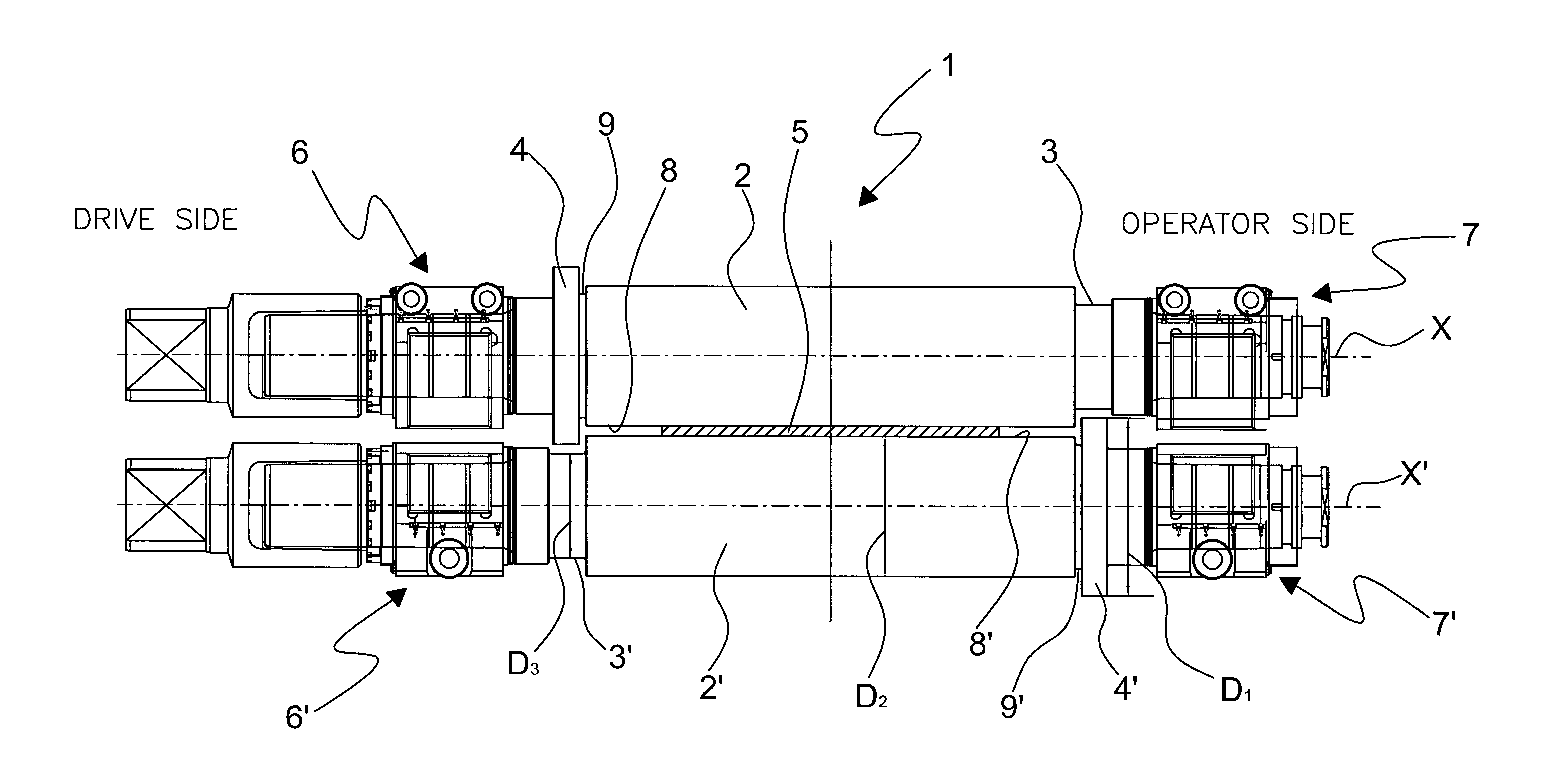
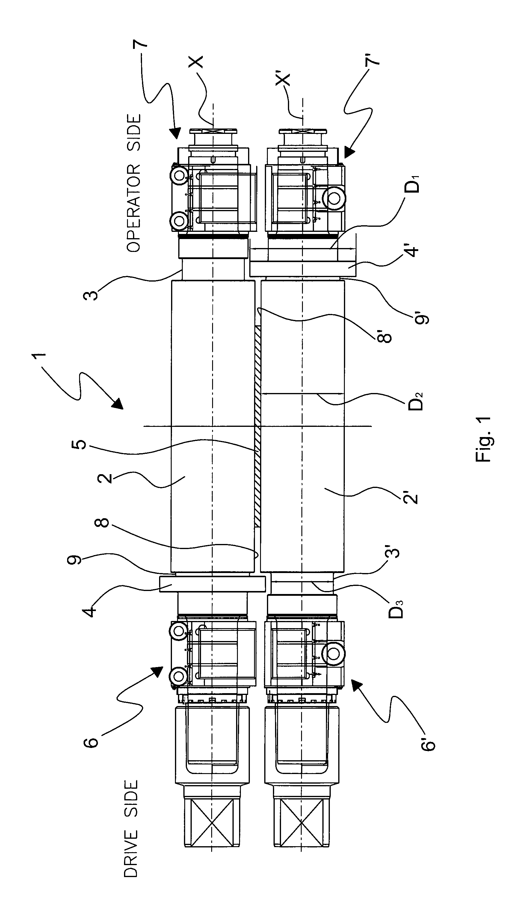
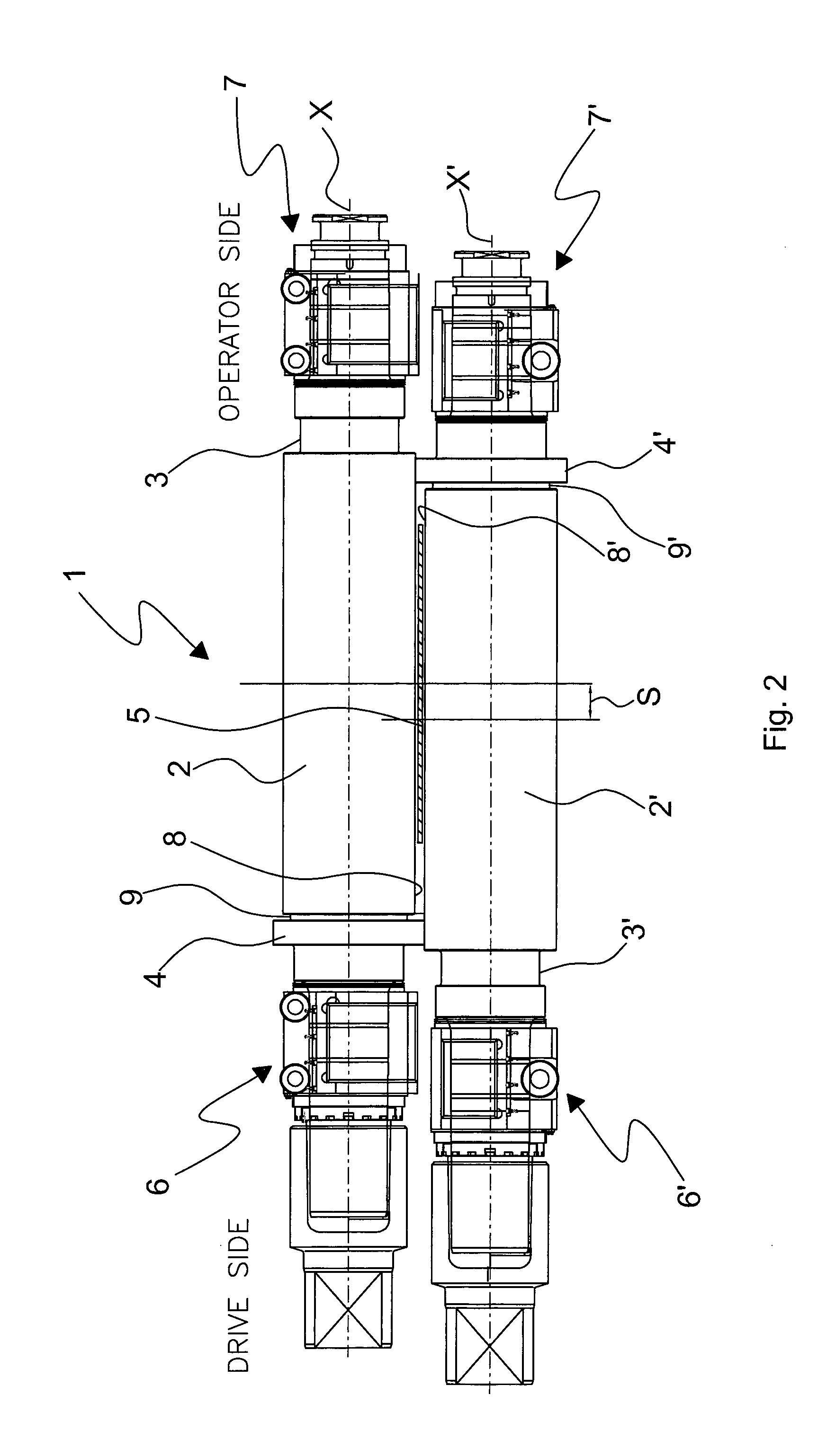
[0040]The figures show a preferred embodiment of a zeroing system of a rolling stand, globally indicated by reference number 1, for allowing zero adjusting or zeroing of the rolling stand after changing the working and / or supporting rolls in the presence of a metallic strip crossing the rolling stand.

[0041]According to one embodiment, the zeroing system of a rolling stand comprises:

[0042]an upper working roll 2 provided at a first end with an annular protrusion or ring or collar 4, having a diameter D1 larger than a diameter D2 of the rolling surface or liner 8 of the same upper working rolling 2, and provided at a second end with a groove 3 having a diameter D3 smaller than said diameter D2;

[0043]a lower working roll 2′ provided at a first end with an annular protrusion or ring or collar 4′, having a diameter D1 larger than a diameter D2 of the rolling surface or liner 8′ of the same lower rolling roll 2′, and provided at a second end with a groove 3′ having diameter D3 smaller tha...


PUM

PropertyMeasurementUnit
diameter D1aaaaaaaaaa
diameter D2aaaaaaaaaa
diameter D3aaaaaaaaaa

Abstract

A zeroing system of a rolling stand which allows to replace the working cylinders or rolls in a four-high rolling stand for hot rolling strips and to subsequently zero the rolling stand without removing the strip from between the rolls themselves during the step of rolling. Furthermore, the system of the invention allows to very rapidly and accurately carry out the zeroing operation, thus increasing the productivity in the entire production system.

Description

FIELD OF THE INVENTION[0001]The present invention relates to a zeroing system of a rolling stand, particularly suitable for zeroing the rolling stand in hot rolling plants without interrupting the rolling process itself.STATE OF THE ART[0002]In rolling plants, the working and / or supporting rolls of the rolling stands must be periodically replaced due to wear.[0003]After replacement, the rolling stand must be zeroed, i.e., the precise position at which the respective surfaces of the upper working roll and the lower working roll come into contact must be defined according to the diameter of the rolls present in the rolling stand (working rolls and supporting rolls). Furthermore, this is needed to guarantee a correct value of the rolled product thickness, at the outlet of the rolling stand, which must be within the required tolerances.[0004]The possibility of zeroing working rolls with material between the rolls is applied in strip cold rolling mills or in process lines by manually pla...

Claims


Application Information

Patent Timeline
Patent Type & Authority Patents(United States)
IPC IPC(8): B21B13/00B21B38/10B21B31/18B21B27/02B21B31/16
CPCB21B13/00B21B38/105B21B27/021B21B31/16B21B31/18B21B2267/06B21B2269/14
Inventor BENEDETTI, GIANPIETROSANDRIN, LUCA
Owner DANIELI & C OFF MEC SPA
Why Eureka
Try Eureka