Flow path control valve

a flow path and control valve technology, applied in the direction of valve housings, water supply installation, operating means/releasing devices, etc., can solve the problems of lowering the reliability of solenoid valve operation, inability to completely select the opening or closing of the flow path, and complicated structure, so as to reduce installation space, prevent the backflow of the working flow, and simplify the structure

Inactive Publication Date: 2008-11-18
JIN KUM SOO
View PDF6 Cites 0 Cited by
  • Summary
  • Abstract
  • Description
  • Claims
  • Application Information

AI Technical Summary

Benefits of technology

[0012]According to the flow path control valve of the present invention constructed as above, a back flow of a working flow is prevented without installation of an additional check valve, resulting in a simplified structure and a reduced installation space. Further, since the flow path control valve is opened or closed by means of the pressure of the working fluid, the flow path control valve can be rapidly and accurately operated and the reliability of the product can also be improved.

Problems solved by technology

Here, since the solenoid valve 43 is constructed to be opened or closed under control according to a detection value from a sensor installed at the air-cooling type heat exchanger 45 or the water-cooling type heat exchanger 46, the sensor malfunctions upon occurrence of a back flow of the working fluid, resulting in incomplete selective opening or closing d the flow path and lowered reliability of the operation d the solenoid valve 43.
Therefore, since the check valve should be additionally installed at the rear of the solenoid valve to prevent the back flow of the working fluid in the prior art, it results in a complicated structure.
Particularly, an air conditioning system employing a large number of solenoid valves and check valves has problems in that its structure is complicated and the number of parts increases, resulting in increased costs.

Method used


Image

  • Flow path control valve
  • Flow path control valve
  • Flow path control valve

Examples


Embodiment Construction

[0025]Hereinafter, preferred embodiments of the present invention will be described in detail with reference to accompanying drawings.

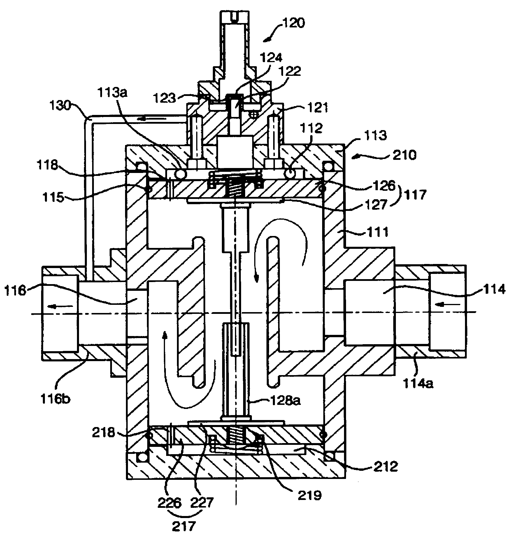
[0026]Referring to FIGS. 5 to 7 showing sectional views of a flow path control valve according to the present invention, the flow path control valve 110 according to the present invention comprises a housing 111 firmed with a valve chamber 112 that can be in fluid communication with an inlet 114 and an outlet 116, an opening / closing member 117 installed movably within the valve chamber 112 for moving between an opening position and a closing position to open or close a passage between the inlet 114 and the outlet 116, an elastic member 119 installed within the valve chamber 112 to bias the opening / closing member 117 toward the closing position, and a solenoid 120 installed at a side of the housing 111 to electromagnetically moving the opening / closing valve 117. A side of the opening / closing member 117 is formed with a pressure equilibrium hole 118 for...


PUM


Abstract

The present invention relates to a flow path control valve capable of preventing a back flow of a fluid by maintaining inner pressure of a valve chamber constant. An object of the present invention is to provide a flow path control valve, which can rapidly and accurately control a flow path for a working fluid and also prevent a back flow of a working fluid without an additional check valve, thereby reducing the size of the product. A flow path control valve of the present invention for achieving the object comprises a housing formed with a valve chamber that can be in fluid communication with an inlet and an outlet; an opening / closing member installed movably within the valve chamber for moving between an opening position and a closing position to open or close a passage between the inlet and the outlet; an elastic member installed within the valve chamber to bias the opening / closing member toward the closing position; and a solenoid installed at a side of the housing to electromagnetically moving the opening / closing valve. A side of the opening / closing member is formed with a pressure equilibrium hole for causing the valve chamber to be in fluid communication with the inlet. A bypass tube is provided to discharge a fluid, which has been introduced into the valve chamber through the pressure equilibrium hole, to the outlet.

Description

TECHNICAL FIELD[0001]The present invention relates to a flow path control valve for electronically controlling opening and closing of a flow path, and more particularly, to a flow path control valve capable of preventing a back flow of a fluid by maintaining inner pressure of a valve chamber constant.BACKGROUND ART[0002]Generally, a flow path control valve for controlling a flow path for a circulating fluid is used in hydraulic pressure generating apparatuses including hydraulic pumps, hydraulic actuators, and pumps. Such a flow path control valve is used in air conditioning facilities, automation facilities or the like so that it can control a flow path through automatic operation thereof or depending on operation conditions in accordance with hydraulic pressure generating apparatuses.[0003]FIGS. 1 and 2 are views showing heating and cooling systems established by a heat pump type air conditioner employing a conventional flow path control valve. As shown in FIG. 1, when the heat pu...

Claims


Application Information

Patent Timeline
Patent Type & Authority Patents(United States)
IPC IPC(8): F16K51/00F16K31/383F16K31/122
CPCF16K31/383Y10T137/7761Y10T137/88054F16K31/406F16K31/122
Inventor JIN, KUM SOO
Owner JIN KUM SOO
Why Eureka
Try Eureka