Pipe joint locking device

a locking device and pipe joint technology, applied in the direction of mechanical control devices, hose connections, instruments, etc., can solve the problems of affecting sealing properties, not taking into account the rotation and twist of the pipe member with respect to the joint member having the external thread, etc., to avoid the possibility of accidental loosening of the pipe joint after tightening and avoid faulty sealing caused by twisting after piping installation.

Inactive Publication Date: 2011-07-19
FUJIKIN INC
View PDF34 Cites 7 Cited by
  • Summary
  • Abstract
  • Description
  • Claims
  • Application Information

AI Technical Summary

Benefits of technology

[0013]According to the pipe joint locking device of the present invention, the first component member including the mounting portion to be mounted to the joint member having the external thread while prevented from relative rotation and the cover portion provided to be contiguous with the mounting portion and to be brought into contact with the outer peripheral face of the joint member having the internal thread from one side and the second component member including the cover portion to be brought into contact with the outer peripheral face of the joint member having the internal thread from the other side are coupled through the coupling portions of the respective component members. Therefore, it is impossible to rotate the joint member having the internal thread with respect to the joint member having the external thread and accidental loosening of the pipe joint after tightening is prevented. Furthermore, the first component member is not rotatable with respect to the joint member having the external thread and the coupling portion of the first component member and the coupling portion of the second component member are coupled to be fixed to the portion of the pipe member protruding from the member having the internal thread. Therefore, rotation of the pipe member with respect to the joint member having the external thread is prevented. Even when a force for rotating the pipe member acts on the pipe member, the force does not affect the seal portion disposed between the joint member having the external thread and the pipe member, faulty sealing caused by a twist after piping installation can be avoided, and the pipe joint can retain its sealing property.

Problems solved by technology

However, rotation and twist of the pipe member with respect to the joint member having the external thread are not taken into consideration at all.
Therefore, if a force for rotating the pipe member acts on the pipe member, the pipe member is rotated or twisted while the seal portion is disposed between the joint member having the external thread and the pipe member and, as a result, the sealing property is impaired.

Method used


Image

  • Pipe joint locking device
  • Pipe joint locking device
  • Pipe joint locking device

Examples


Embodiment Construction

[0048]An embodiment of the present invention will be described below with reference to the drawings.

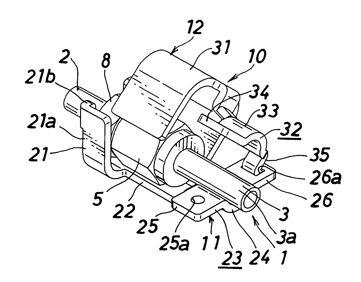
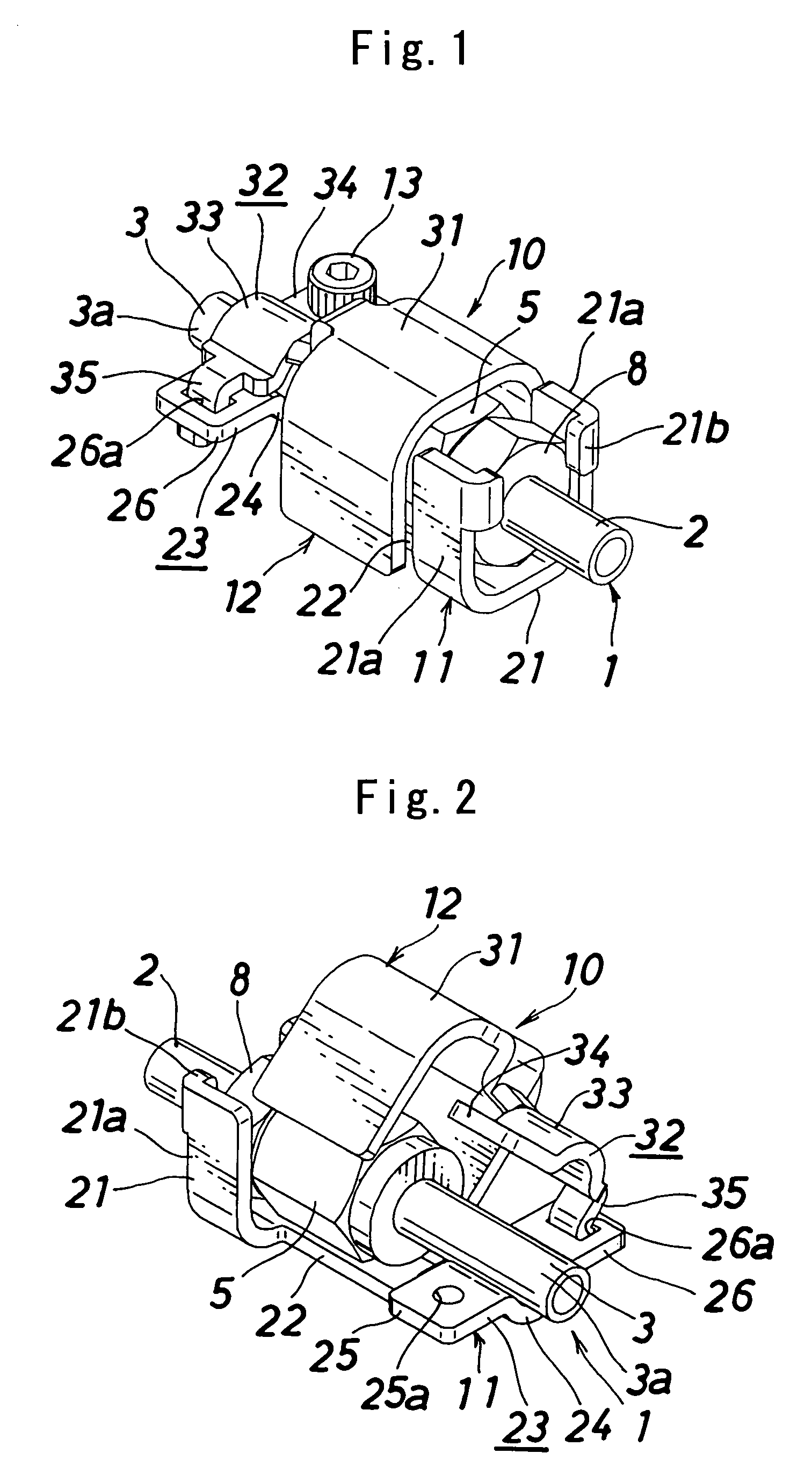
[0049]FIG. 9 shows an example of a pipe joint to which a pipe joint locking device of the present invention is applied. In this drawing, the pipe joint (1) is formed of a first pipe-shaped joint member (joint member having an external thread) (2), a second pipe-shaped joint member (pipe member) (3), an annular gasket (seal portion) (4) disposed between a left end face of the first pipe-shaped joint member (2) and a right end face of the second pipe-shaped joint member (3), a cap nut (joint member having an internal thread) (5) fitted by screwing over the first pipe-shaped joint member (2) from the second pipe-shaped joint member (3) side, a retainer (6) for retaining the gasket (4) and retained by the first pipe-shaped joint member (2), and a thrust ring (7) disposed between a top wall of the cap nut (5) and a flange portion of the second pipe-shaped joint member (3). The end faces of...


PUM


Abstract

A pipe joint locking device which prevents accidental loosening of a pipe joint after tightening and with which a sealing property of a seal portion of the pipe joint is not impaired even if a force for rotating a pipe member acts on the pipe member. The device is formed of: a first component member 11 including a mounting portion 21 to be mounted to a joint member 2 having an external thread while prevented from relative rotation, a cover portion 22 to be brought into contact with an outer peripheral face of a cap nut 5 from a lower side, and a coupling portion 23 to be brought into contact with a pipe member 3 from the lower side; and a second component member 12 including a cover portion 31 to be brought into contact with the outer peripheral face of the cap nut 5 from an upper side and a coupling portion 32 to be brought into contact with the pipe member 3 from the upper side. The coupling portion 23 of the first component member 11 and the coupling portion 32 of the second component member 12 are coupled to be fixed to a portion 3a of the pipe member 3 protruding from the cap nut 5.

Description

BACKGROUND OF THE INVENTION[0001]1. Field of the Invention[0002]The present invention relates to a pipe joint locking device for preventing accidental loosening of a pipe joint after tightening.[0003]2. Description of the Related Art[0004]In a pipe joint, a joint member having an internal thread (cap nut) is tightened onto a joint member having an external thread and, as a result, the joint member having the external thread and a pipe member are connected while facing each other through a seal portion. As a locking device (locking clamp) for preventing accidental loosening of the pipe joint after tightening, there is a device, as disclosed in Patent Document 1, formed of: a first clamping member including mounting portions to be mounted while prevented from relative rotation to engaging portions (wrench flats) provided to a joint member having an external thread and a coupling portion provided to be contiguous with the mounting portions and to be brought into contact with an outer p...

Claims


Application Information

Patent Timeline
Patent Type & Authority Patents(United States)
IPC IPC(8): F16L35/00F16K35/00
CPCF16L19/005F16L27/0832F16L19/046F16L19/0286Y10T70/5637Y10T70/5628Y10T70/5867F16L19/00F16L15/00
Inventor TSUBOTA, KENJIYAMAJI, MICHIO
Owner FUJIKIN INC
Why Eureka
Try Eureka