Battery and system power selector integration scheme

a power selector and battery technology, applied in the field of information handling systems, can solve the problems of not offering sufficient protection in the operation of the internal switch, affecting the reliability of the battery, and requiring a lot of circuit implementation, so as to reduce the number of components, reduce the occurrence of operating conflicts, and improve reliability.

Inactive Publication Date: 2011-07-19
DELL PROD LP
View PDF20 Cites 9 Cited by
  • Summary
  • Abstract
  • Description
  • Claims
  • Application Information

AI Technical Summary

Benefits of technology

Several advantages are achieved by the method and system according to the illustrative embodiments presented herein. The embodiment...

Problems solved by technology

In the past, the rechargeable batteries (also known as “dumb” batteries) provided an unpredictable source of power for the portable devices, because typically, a user of the device powered by the battery had no reliable advance warning that the energy supplied by the rechargeable battery was about to run out.
While smart selector circuits serve an important purpose, they suffer certain deficiencies.
For example, smart selector circuits typically include several switches each including back-to-back FET's to control which battery is being charged or discharged, making it a fairly expensive circuit to implement.
While the mutual detection technique reduces the number of switches, it may not offer sufficient protection in the operation of the internal switch in case of conflicts.
For example, the functionality provided by some of the removed components may not be adequately included in the improved design.
This may result in both batteries being charged simultaneously,...

Method used


Image

  • Battery and system power selector integration scheme
  • Battery and system power selector integration scheme
  • Battery and system power selector integration scheme

Examples


Embodiment Construction

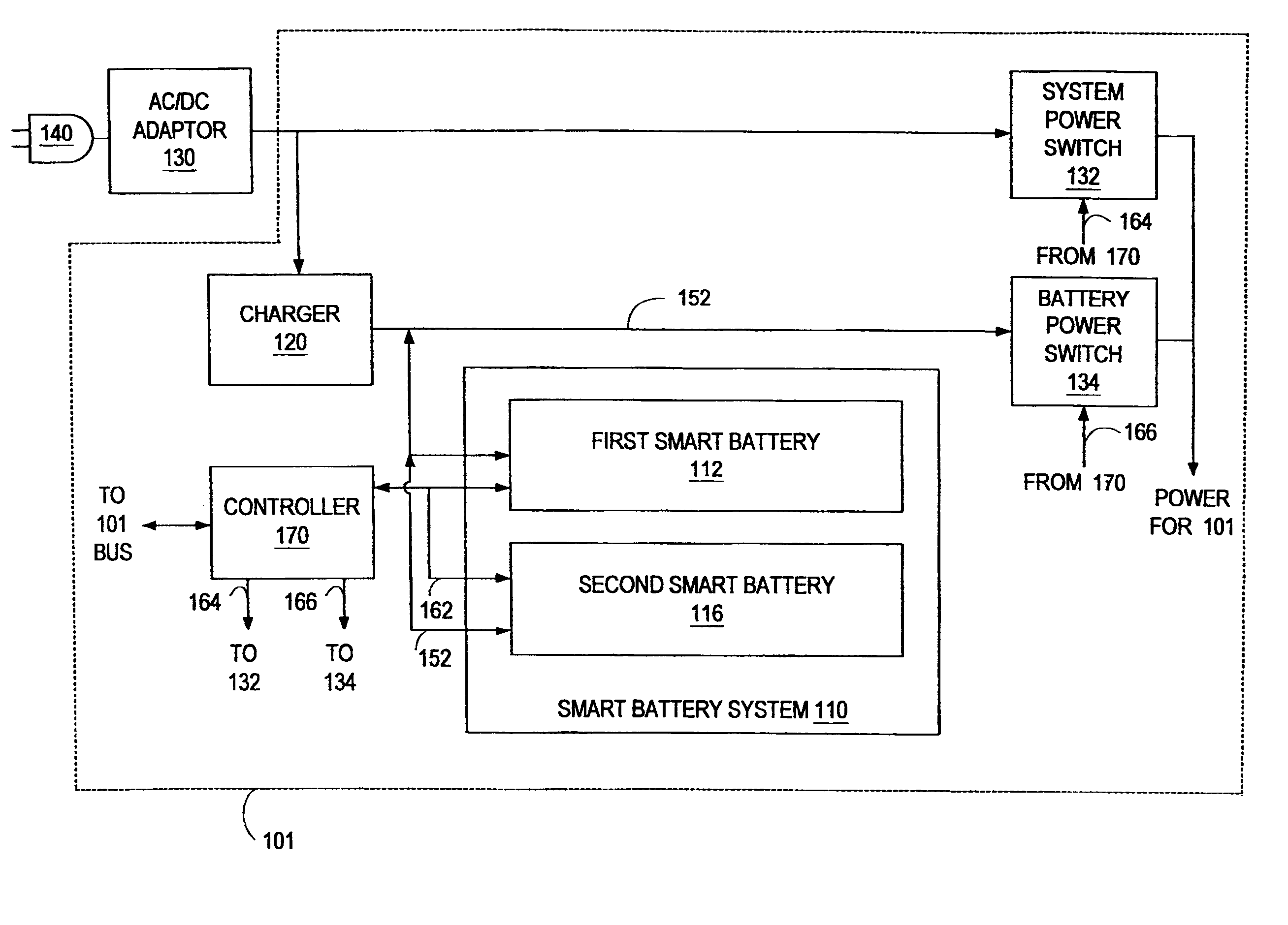
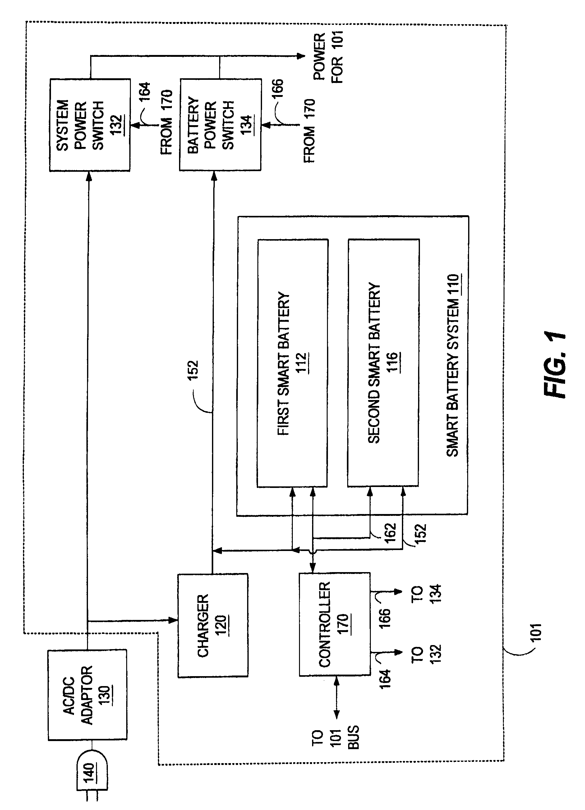
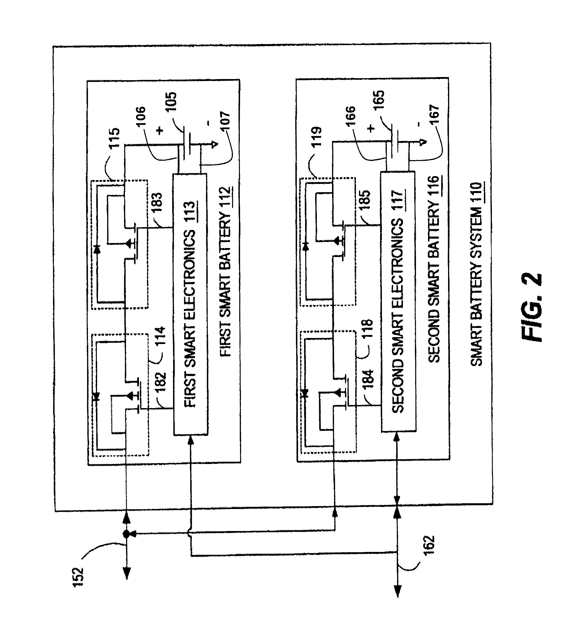
Novel features believed characteristic of the present disclosure are set forth in the appended claims. The disclosure itself, however, as well as a preferred mode of use, various objectives and advantages thereof, will best be understood by reference to the following detailed description of an illustrative embodiment when read in conjunction with the accompanying drawings. The functionality of various devices or components described herein may be implemented as hardware (including circuits) and / or software, depending on the application requirements.

Each smart battery in a portable device imposes certain operating constraints on the operation and selection of the AC and / or the smart battery system power source, especially when two or more smart batteries are present in the smart battery system. Failure to impose the operating constraints, while attempting to reduce the number of components, may result in generating the operating conflicts. There is a need for integrating the selectio...


PUM


Abstract

For operating each smart battery included in a smart battery system, the smart battery is initialized prior to the smart battery being electrically coupled to the smart battery system. The smart battery system or an external power source is selected to provide power to an information handling system device. The smart battery includes an electronics device, a charge switch and a discharge switch. The electronics device operates the charge and discharge switches to jointly control an operating condition of the smart battery in response to receiving a control input from a controller of the device. The charge and discharge switches are closed in response to the electronics device and the controller being in agreement to charge the first smart battery. The charge or the discharge switch is opened in response to either the electronics device or the controller directing either of the switches to be opened.

Description

BACKGROUNDThe present disclosure relates generally to information handling systems, and more particularly to techniques for integrating selection and operation of power from battery and system power sources commonly used to provide energy to portable information handling system components such as notebook computers, personal digital assistants, cellular phones and gaming consoles.As the value and use of information continues to increase, individuals and businesses seek additional ways to process and store information. One option available to users is information handling systems. An information handling system (IHS) generally processes, compiles, stores, and / or communicates information or data for business, personal, or other purposes thereby allowing users to take advantage of the value of the information. Because technology and information handling needs and requirements vary between different users or applications, IHSs may also vary regarding what information is handled, how the...

Claims


Application Information

Patent Timeline
IPC IPC(8): H02J7/00H02J7/34H02J13/00
CPCH02J7/0022H02J7/0031H02J7/0068H02J7/34H02J13/0003H02J2007/0098H01M10/4257H02J7/00309Y02E60/10H02J7/0013
Inventor BREEN, JOHN J.MCDONALD, BRENT A.
Owner DELL PROD LP
Why Eureka
Try Eureka