Inspection methods for defects in electrophoretic display and related devices

a technology of electrophoretic display and inspection method, which is applied in the direction of static indicating device, individual semiconductor device testing, instruments, etc., can solve the problem that the use of temporary conductive layer is not an efficient and cost-effective way for testing and inspection

Inactive Publication Date: 2011-07-19
E INK CALIFORNIA
View PDF33 Cites 128 Cited by
  • Summary
  • Abstract
  • Description
  • Claims
  • Application Information

AI Technical Summary

Problems solved by technology

The use of a temporary conductive layer therefore is not an efficient and cost-effective way for testing and inspection.

Method used


Image

  • Inspection methods for defects in electrophoretic display and related devices
  • Inspection methods for defects in electrophoretic display and related devices
  • Inspection methods for defects in electrophoretic display and related devices

Examples


Embodiment Construction

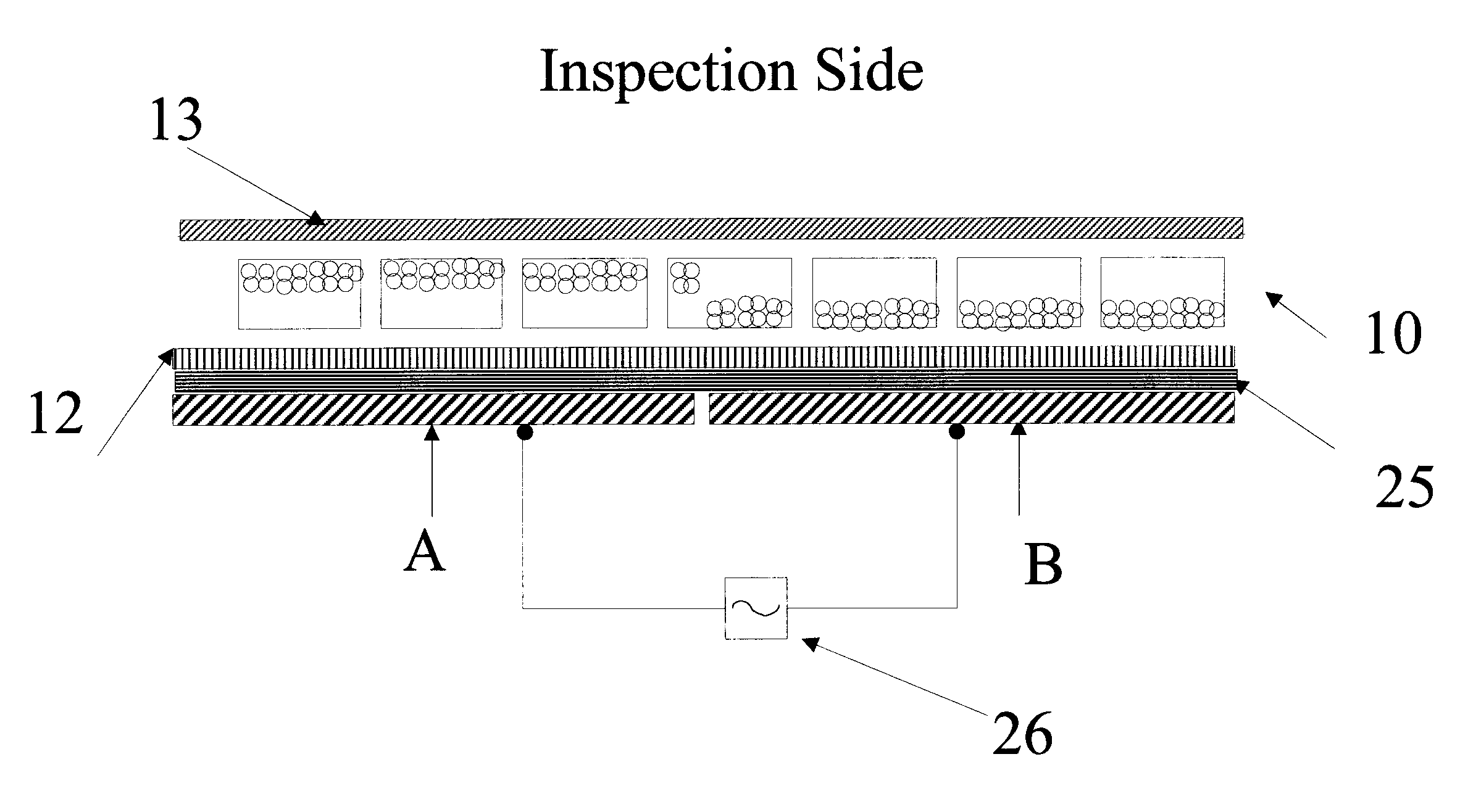
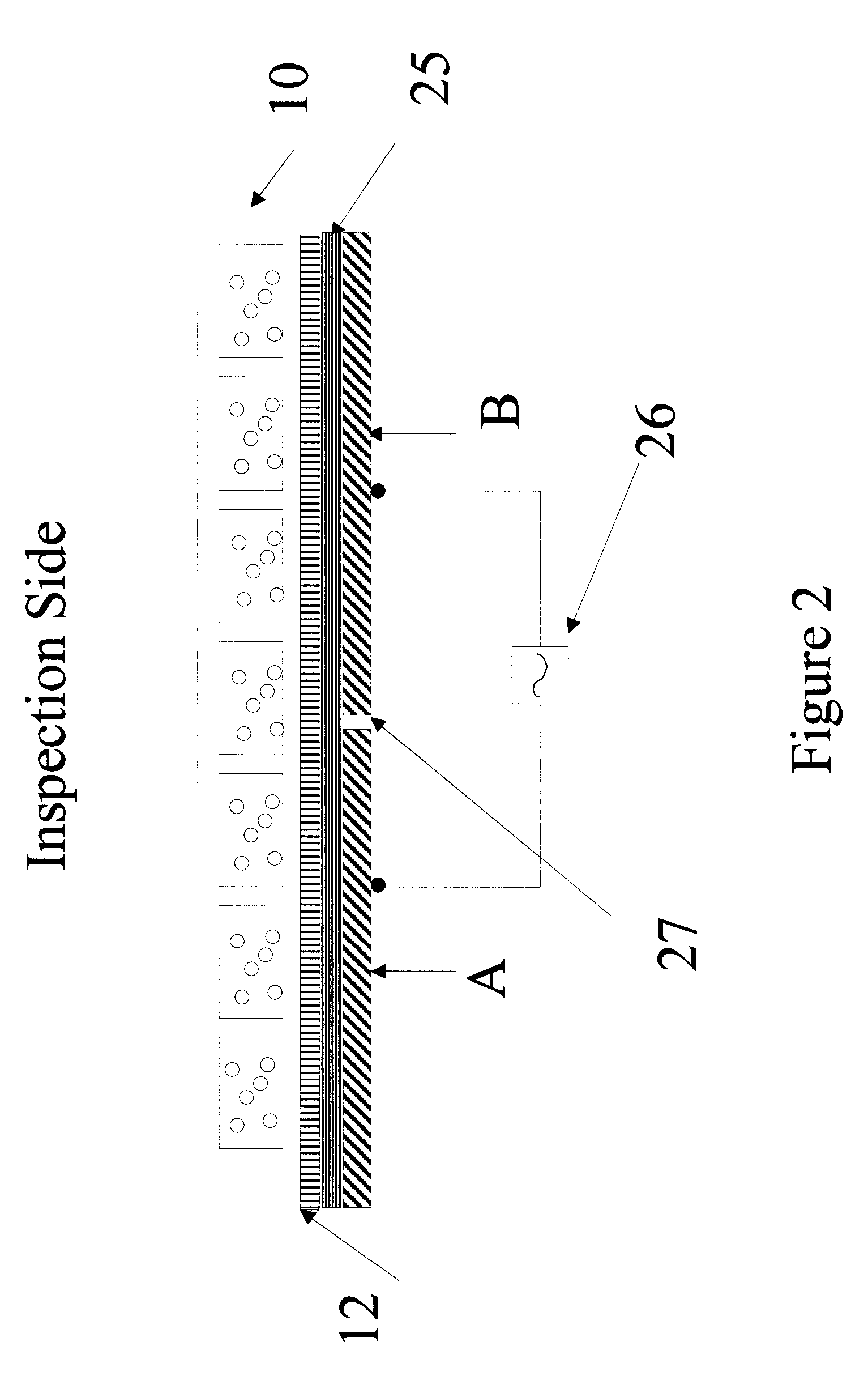
[0022]The present invention is directed to an inspection method for inspecting defects of a display panel, wherein said display panel comprises a layer of display cells filled with an electrophoretic fluid. The method comprises applying a voltage difference to two testing electrodes which are in contact with the display panel, and identifying defects of the display panel.

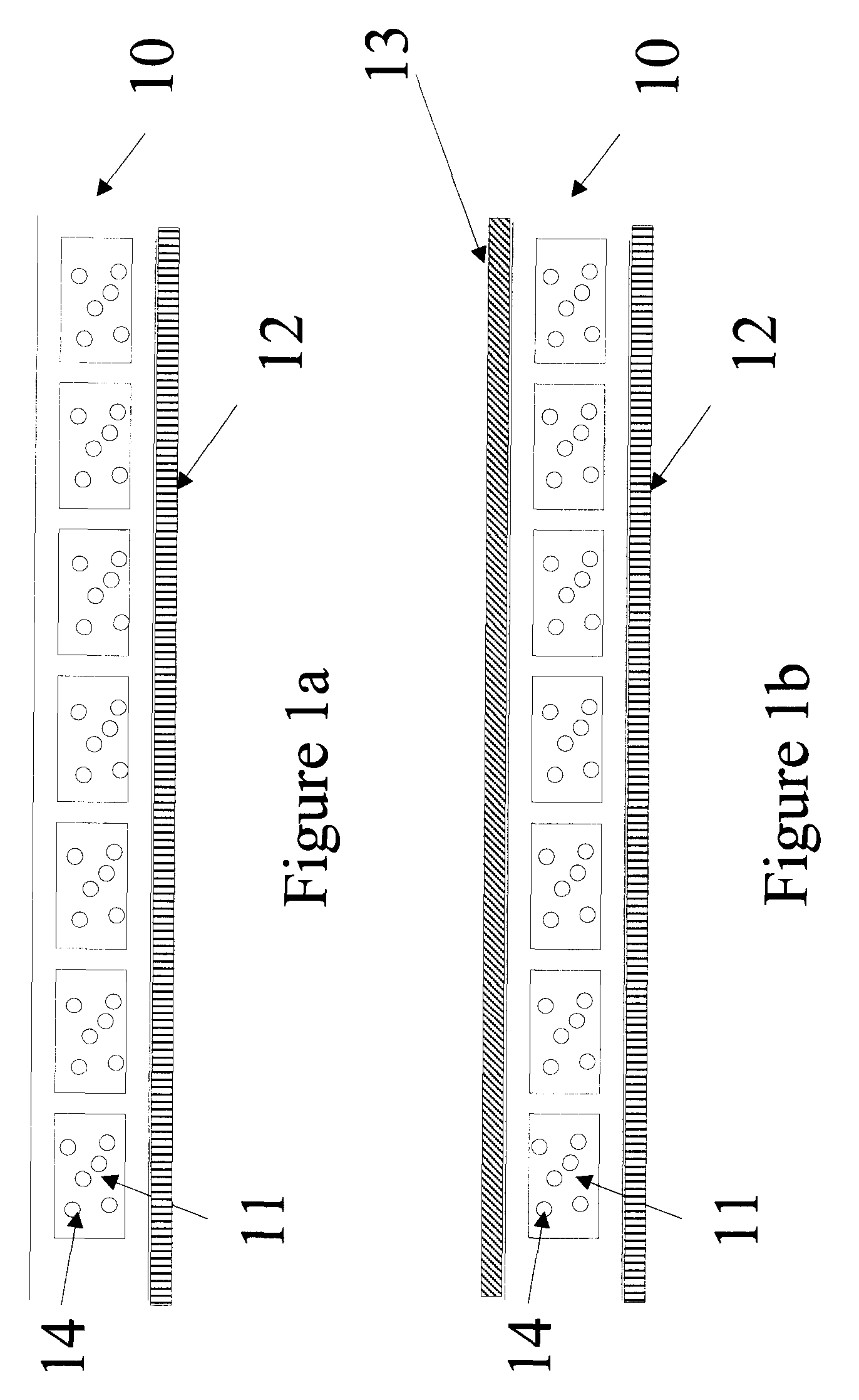
[0023]The present inspection methods may be used on a display panel in a variety of forms. For example, FIG. 1a shows a display panel comprising a layer of display cells (10) which are filled with an electrophoretic fluid (11) comprising charged pigment particles (14) dispersed in a dielectric solvent. The display panel may be tested directly with a testing method of the present invention. However it is preferred that the display panel is protected by a contact film (12) during testing as shown in the figure.

[0024]Suitable materials for the contact film may include, but are not limited to, polyimide, polysulfone, po...


PUM


Abstract

The present invention relates to methods for inspection of defects in an electrophoretic display and related devices. The method may be carried out with one or more testing electrodes. The method comprises applying a voltage difference to two testing electrodes which are in contact with the display panel, or applying a voltage difference to a testing electrode and a electrode layer. The methods may be applied in in-line or off-line inspection of a display panel.

Description

[0001]This application claims priority to U.S. provisional application No. 60 / 790,098, filed Apr. 7, 2006, the content of which is incorporated herein by reference in its entirety.FIELD OF THE INVENTION[0002]The present invention provides methods for inspection of defects in an electrophoretic display and related devices.BACKGROUND OF THE INVENTION[0003]The electrophoretic display (EPD) is a non-emissive device based on the electrophoresis phenomenon influencing the migration of charged pigment particles in a solvent, preferably in a dielectric solvent. More specifically, an electrophoretic fluid comprising charged pigment particles dispersed in a dielectric solvent is enclosed between two electrode plates. At least one of the electrode plates is transparent and such a transparent plate is usually the viewing side. When a voltage difference is imposed between the two electrode plates, the charged pigment particles migrate by attraction to the electrode plate of polarity opposite tha...

Claims


Application Information

Patent Timeline
Patent Type & Authority Patents(United States)
IPC IPC(8): G01R31/302
CPCG09G3/006G09G3/344
Inventor WANG, WANHENGCHAUG, YI-SHUNGCHEN, YAJUANKANG, GARY YIH-MINGYEN, JIMMY
Owner E INK CALIFORNIA
Why Eureka
Try Eureka