Polarization maintaining optical fiber polarizer

a technology of maintaining optical fiber and polarizer, applied in the field of polarizers, can solve the problems of undesirable reflection, optical loss, and relatively expensive and difficult construction

Active Publication Date: 2011-07-19
CHIRAL PHOTONICS
View PDF9 Cites 25 Cited by
  • Summary
  • Abstract
  • Description
  • Claims
  • Application Information

AI Technical Summary

Problems solved by technology

The main disadvantage of this type of polarizer is that it is relatively expensive and difficult to construct.
Furthermore, the lens-based polarizer interrupts the optical fiber leading to optical loss, undesirable reflection, and reduced stability.
Finally, the lens-based polarizer introduces a device into the fiber that is larger than the fiber, thereby causing potential space issues.
However, the coil-based polarizer suffered from another significant drawback—the coil element around which the fiber needed to be wrapped was typically many centimeters in diameter making the coil-based polarizer very bulky and difficult or impossible to use in many applications.
The fact that polarization conversion only happens across a narrow frequency band, is one of the chief limitations and drawbacks of quarter-wave plates and quarter-wave plate-type devices.
However, the various embodiments of both solutions disclosed in the above-discussed Adjustable Polarizer and Chiral Polarizer patents, involved the use of chiral fiber structures which may be difficult to fabricate in-line with conventional fibers (and which would typically be spliced in-line with conventional fibers during use), and which, in certain embodiments thereof, would need to utilize one or more optical fiber couplers (such as disclosed in the commonly assigned U.S. Pat. No. 7,308,173, issued on Dec. 11, 2007, entitled “Optical Fiber Coupler with Low Loss and High Coupling Coefficient and Method of Fabrication Thereof”).

Method used


Image

  • Polarization maintaining optical fiber polarizer
  • Polarization maintaining optical fiber polarizer
  • Polarization maintaining optical fiber polarizer

Examples


Embodiment Construction

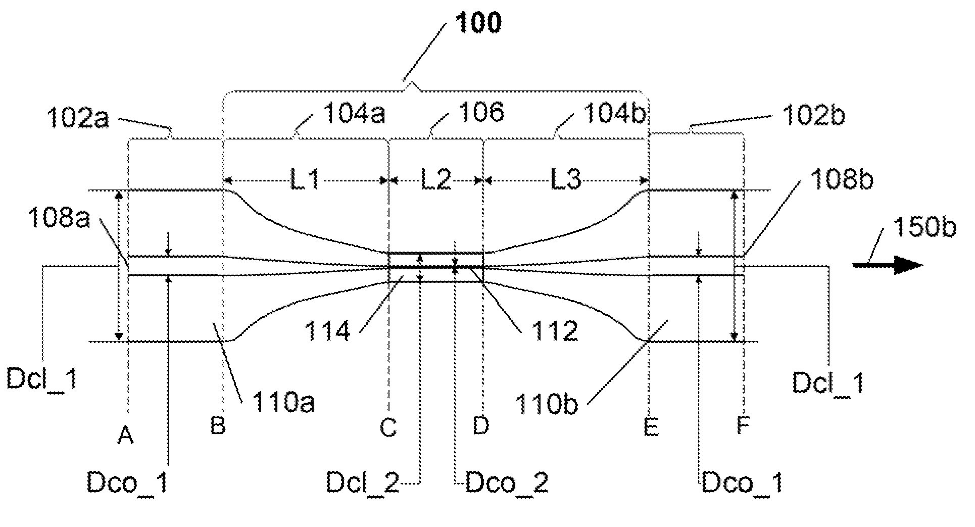
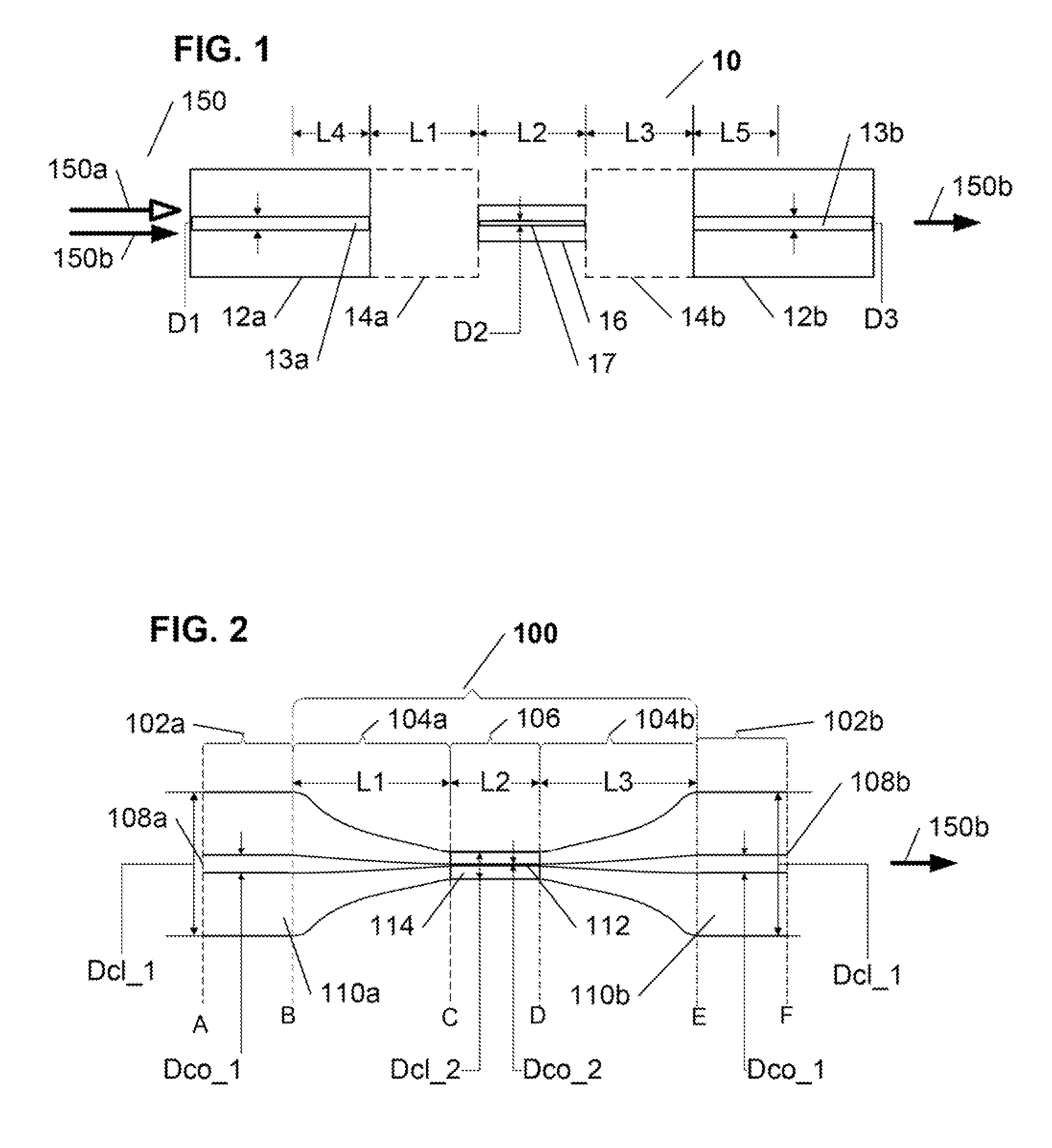
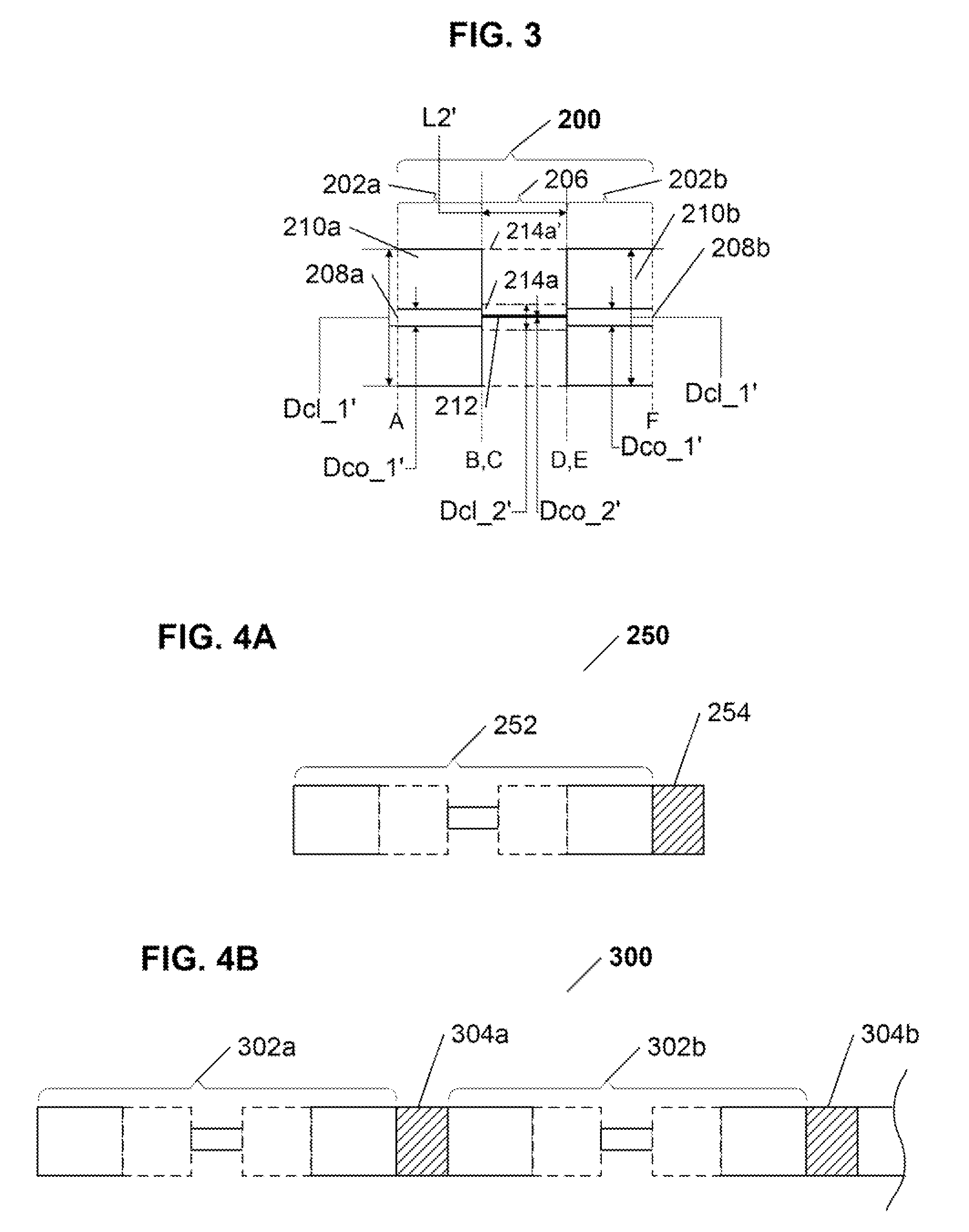
[0019]The present invention is directed to a novel in-fiber polarizer implemented in an optical fiber structure based on a polarization maintaining (“PM”) optical fiber, and that is configured to impart a predetermined desired polarization to a light signal transmission of a predetermined at least one wavelength transmitted therethrough. In summary, the inventive polarizer comprises a PM optical fiber structure, with an entry end for receiving incident light and an exit end for outputting polarized light, having an optical fiber core, having at least one core mode and a core propagation constant, surrounded by a cladding, having at least one cladding mode and a cladding propagation constant, that further comprises a reduced core diameter region of a predetermined length between its entry and exit ends, wherein various predefined parameters of the modified PM optical fiber structure, including but not being limited to, the core and cladding propagation constants, the value of the red...


PUM


Abstract

A novel in-fiber polarizer is provided that is implemented in an optical fiber structure based on a polarization maintaining (“PM”) optical fiber, and that is configured to impart a predetermined desired polarization to a light signal transmission of a predetermined at least one wavelength transmitted therethrough. The inventive polarizer comprises a PM optical fiber structure, with an entry end for receiving incident light and an exit end for outputting polarized light, having an optical fiber core, having at least one core mode and a core propagation constant, surrounded by a cladding, having at least one cladding mode and a cladding propagation constant, that further comprises a reduced core diameter region of a predetermined length between its entry and exit ends, wherein various predefined parameters of the modified PM optical fiber structure, including but not being limited to, the core and cladding propagation constants, the value of the reduced core diameter, and the length of the reduced core diameter region are selected and configured to produce a constructive interference for one light polarization of the input light signal, corresponding to the desired polarization, and to produce a destructive interference for a polarization orthogonal to the desired polarization, to thereby only output, at the polarizer exit end, the desired polarization component of the light signal transmission at the at least one wavelength. Additional embodiments of the inventive polarizer include multiple sequential polarizer structures with specially configured interconnects.

Description

CROSS REFERENCE TO RELATED APPLICATIONS[0001]The present patent application claims priority from the commonly assigned U.S. provisional patent application 61 / 138,912 entitled “Polarization Maintaining Optical Fiber Polarizer”, filed Dec. 18, 2008.FIELD OF THE INVENTION[0002]The present invention relates generally to polarizers, and more particularly to a polarizer based on a polarization maintaining optical fiber, that is capable of being fabricated and / or positioned in-line with the optical fiber itself, and that would be relatively inexpensive to produce.BACKGROUND OF THE INVENTION[0003]Any device that requires polarized light, uses one or more polarizers. Polarizers have many industrial applications. For example, polarizers may be utilized in electro-optical modulators and laser subsystems. In essence, a polarizer eliminates an undesirable light component of a first polarization, and allows a desirable light component of a second polarization to pass through.[0004]Of particular i...

Claims


Application Information

Patent Timeline
Patent Type & Authority Patents(United States)
IPC IPC(8): G02B6/24
CPCG02B6/2726
Inventor ZHANG, SHENGKOPP, VICTOR IL'ICH
Owner CHIRAL PHOTONICS
Why Eureka
Try Eureka