Mounting strip for mounting a formed part on a chassis body of a motor vehicle

a technology for mounting strips and formed parts, which is applied in the direction of sheet joining, dowels, applications, etc., can solve the problems of increasing the number of mounting strips, so as to achieve simple assembly and disassembly of mounting strips, the overall strength of the mounting strips is not reduced, and the effect of reducing the stress on the mounting strips

Active Publication Date: 2011-07-26
PEGUFORM
View PDF12 Cites 1 Cited by
  • Summary
  • Abstract
  • Description
  • Claims
  • Application Information

AI Technical Summary

Benefits of technology

[0013]As the attachment pins are formed directly at the ribs according the invention, the different thermal expansion that is generated is transmitted onto the ribs, which thus can yield due to the weakened areas in order to compensate any differences in the thermal expansion and without the stress at the mounting strip to the point where the formation of cracks in the plastic material occurs. The ribs are hereby formed so strong that the overall strength of the mounting strip is essentially not reduced. Since the weakened areas can compensate for stresses in the length direction, it is now also possible to install relatively simply constructed catch elements for attachment of the mounting strip at the vehicle body, because the catch elements themselves must no longer compensate or absorb any expansion differences due to their transmission into the weakened areas.
[0014]In this manner, it is possible to attach even formed parts of length dimensions at the vehicle body without any problems and without the danger that the attachment of the formed part will be compromised by the differential thermal expansion. Depending on the length dimension of the formed part to be mounted, it can be advantageous to utilize a mounting strip that does not correspond to the length of the formed part but that the mounting arrangement is distributed onto several smaller mounting strips that are serially mounted next to each other. Thus, the entire expansion difference is distributed onto each of the mounting strips, whereby the stresses to which the mounting strip is subjected are reduced.
[0015]An advantageous embodiment of the mounting pins provides that they are configured as equal-sided cones with open sides whereby the open sides of the pin are arranged in a bridge-like manner between two neighboring webs and formed directly onto them. With these features of the pin a simple assembly and disassembly of the mounting strip is realized, since the so-configured pins are easily pressed together for engagement into or removal from the engagement openings.

Problems solved by technology

A disadvantage of this arrangement is the relatively extensive mounting work, since each single attachment a clip has to be attached to the auto body.
A further disadvantage lies in the fact that due to tolerance fluctuations the single clips, with respect to their part that has to be mounted, do not always provide locational exactness, which makes mounting more difficult and which also can make the mounted part look unsightly, because in such a case, the joint between the formed part and the vehicle body follows an irregular pattern.
In this manner, while the mounting work can thus be facilitated, the problem with precisioning the position of the formed parts is thereby not solved, as such formed parts are normally unitary pieces of relatively large dimension and the imprecision of their positioning is even increased due to tolerance fluctuations that occur during manufacturing.
In addition, in the case where large-dimensioned formed parts of plastic material are involved that include lock elements directly formed at the formed part and which are to be attached for example at metal parts of the vehicle body, the different thermal expansions of metal and plastic have a negative impact and are especially noticeable.
Also, formed or molded parts form plastic material that are very precisely adapted with little tolerance can cause the formation of cracks due to the differential thermal expansion, whereby finally the stability of the attachment is in peril.
On the other hand, attempts to balance this disadvantage with increased tolerances jeopardizes the precision in positioning the part
The mounting arrangement that is described there, while user-friendly and precisely located, can however still lead to problems due to the differential in the thermal expansion of metal and plastic.
In addition, the attachment of a mounting strip at the vehicle body is relatively complex.

Method used


Image

  • Mounting strip for mounting a formed part on a chassis body of a motor vehicle
  • Mounting strip for mounting a formed part on a chassis body of a motor vehicle
  • Mounting strip for mounting a formed part on a chassis body of a motor vehicle

Examples


Embodiment Construction

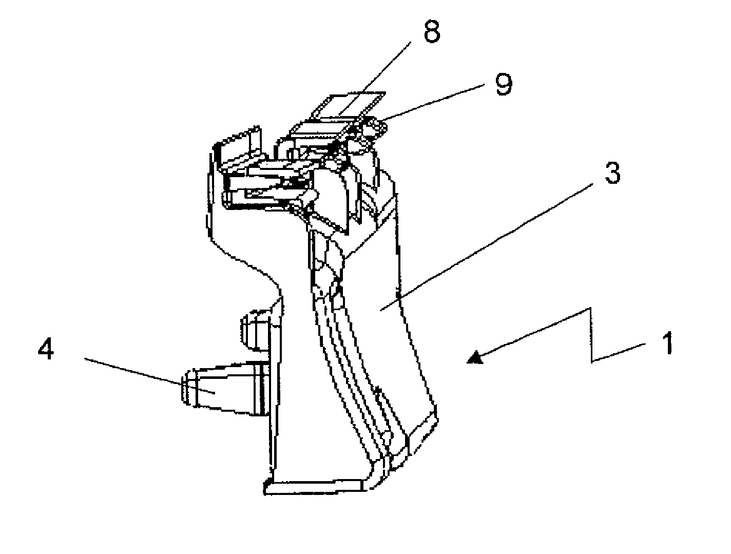
[0024]FIG. 1 shows in a perspective side view and overview of the mounting strip 1 with the extended strip-shaped basic body 3, which, in the upper region of the front side facing the formed part includes guide tracks 8 and snap-in tongues 9 for receiving and fixing formed part 2. At the side of the basic body 3 facing the vehicle body pins 4 are shown which act as locking elements for holding the mounting strip 1 in place in the corresponding openings in the vehicle body, whereby the pins 4 are directly formed onto the basic body 3.

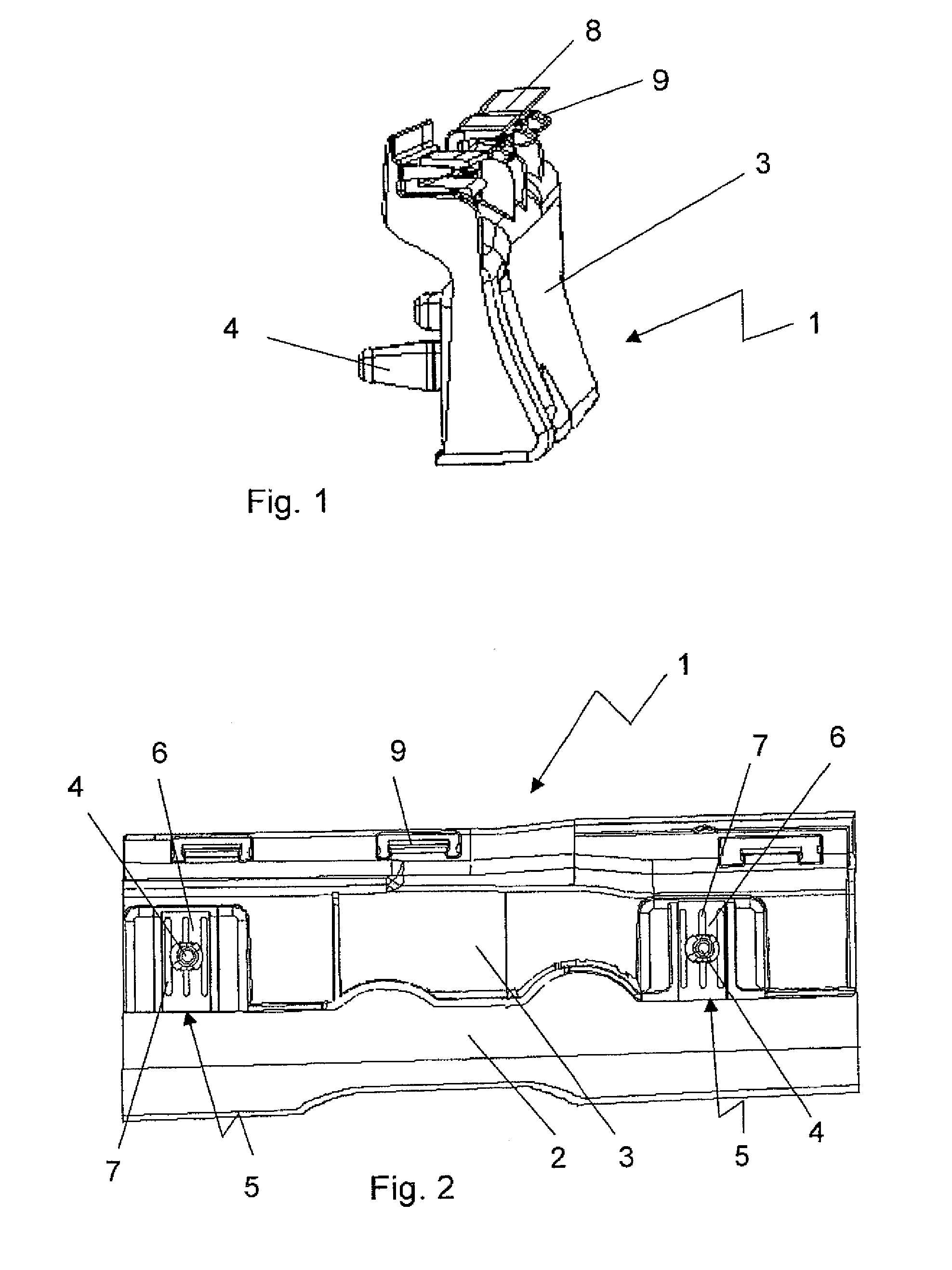
[0025]FIG. 2 shows a rear view of mounting strip 1 with the clamped-in formed part 2. In this top view, the weakened parts are seen with ribs 6 arranged vertical relative to the longitudinal direction and formed by means of slot-shaped recesses 7 that also extend vertical to the longitudinal direction. In the embodiment as shown in FIG. 2 of the present invention, three slot-shaped recesses 7 are provided, which form two rib-shaped webs 6 where the pin 4...


PUM


Abstract

A mounting strip for mounting a formed part on a body of a motor vehicle includes a strip-shaped basic body, a plurality of pins formed directly at the rear side of the basic body as locking elements for holding the mounting strip in corresponding openings in the motor vehicle body; and attachment elements formed at the front side of the basic body for receiving and holding in place the formed part, wherein the mounting strip comprises weakened areas located in direct proximity to the formed on pins and including ribs extending vertical relative to the longitudinal direction of the mounting strip.

Description

CROSS-REFERENCES TO RELATED APPLICATIONS[0001]This application is the U.S. National Stage of International Application No. PCT / EP2009 / 000708, filed Feb. 4, 2009, which designated the United States and has been published as International Publication No. WO 2009 / 106210 and which claims the priority of European Patent Application No. 08 003658.5, filed Feb. 28, 2008, pursuant to 35 U.S.C. 119(a)-(d).BACKGROUND OF THE INVENTION[0002]The present invention refers to a mounting strip for mounting a formed part on a body of a motor vehicle whereby the mounting strip comprises a strip-shaped basic body.[0003]Generic mounting arrangements are known in multiple embodiments for the attachment or mounting of formed parts, such as a bumpers, paneling or cover strips. Oftentimes single clips are utilized for these purposes, which are applied separately at the vehicle body and onto which the mounting arrangement or the mounting strip is attached. A disadvantage of this arrangement is the relatively...

Claims


Application Information

Patent Timeline
Patent Type & Authority Patents(United States)
IPC IPC(8): F16B5/12
CPCB60R13/0206F16B21/088F16B5/126Y10T24/309
Inventor HAPPLE, WOLFGANG
Owner PEGUFORM
Why Eureka
Try Eureka