Device and method for measuring compressive force of flexible linear body

a linear body and flexible technology, applied in the direction of force measurement by measuring optical properties, instruments, force/torque/work measurement apparatus, etc., can solve the problems of conventional linear body, vessel itself may become thinner, and the diameter of the vessel is not necessarily uniform, so as to improve the compressive force, the effect of detecting a degree of bending and cost effectiveness

Inactive Publication Date: 2011-07-26
NAGOYA INSTITUTE OF TECHNOLOGY +1
View PDF29 Cites 52 Cited by
  • Summary
  • Abstract
  • Description
  • Claims
  • Application Information

AI Technical Summary

Benefits of technology

[0028]As described above, according to the measurement device of the present invention, the sensor can detect a degree of bending of the linear body when compressive force in the direction of longitudinal axis is applied to the linear body as a result of contact of the tip end of the linear body with the obstacle. Then, the detected degree of bending of the linear body is converted into compressive force in the direction of longitudinal axis applied to the linear body, so that presence of the obstacle in a direction of travel of the linear body can be sensed based on increase in the compressive force. In addition, as the same measurement device is applicable to linear bodies of various shapes or materials, cost effectiveness is achieved.

Problems solved by technology

In addition, a diameter of the vessel is not necessarily uniform, and the vessel itself may become thinner or a diameter of the vessel may be made smaller by an obstacle located in the vessel such as a thrombus in a blood vessel.
A conventional linear body, however, has not been provided with means for sensing a condition in a direction of travel of the linear body, and it has been necessary to use operator's intuition in operating the linear body and the operator has had to be skilled in the operation for guiding the linear body from outside the body.

Method used


Image

  • Device and method for measuring compressive force of flexible linear body
  • Device and method for measuring compressive force of flexible linear body
  • Device and method for measuring compressive force of flexible linear body

Examples


embodiment 1

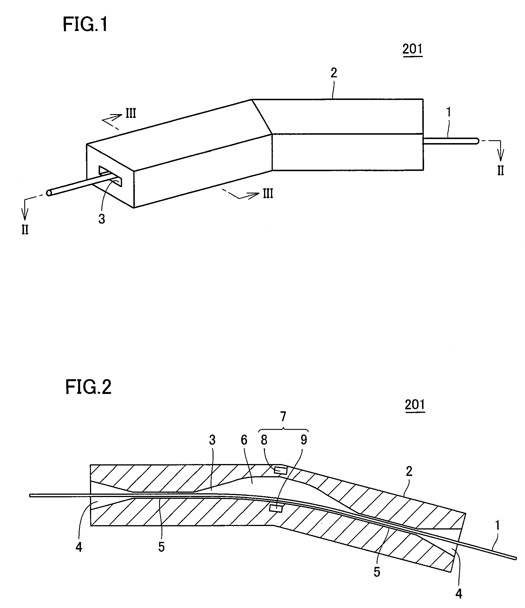
[0063]FIG. 1 is a schematic diagram showing appearance of a main body of a measurement device according to Embodiment 1 representing one embodiment of the present invention. In FIG. 1, a measurement device 201 includes a measurement device main body 2, and in measurement device main body 2, a through hole 3 through which linear body 1 having flexibility passes is formed.

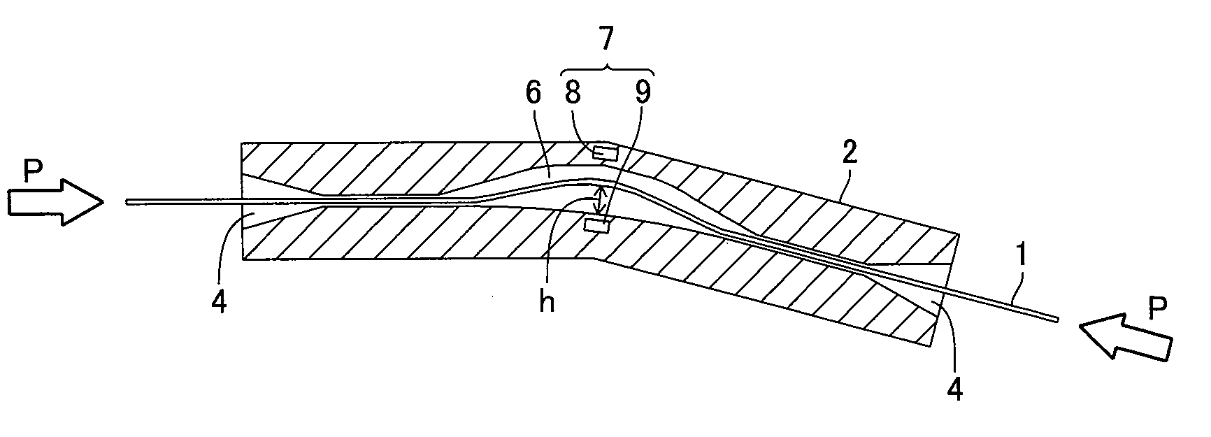
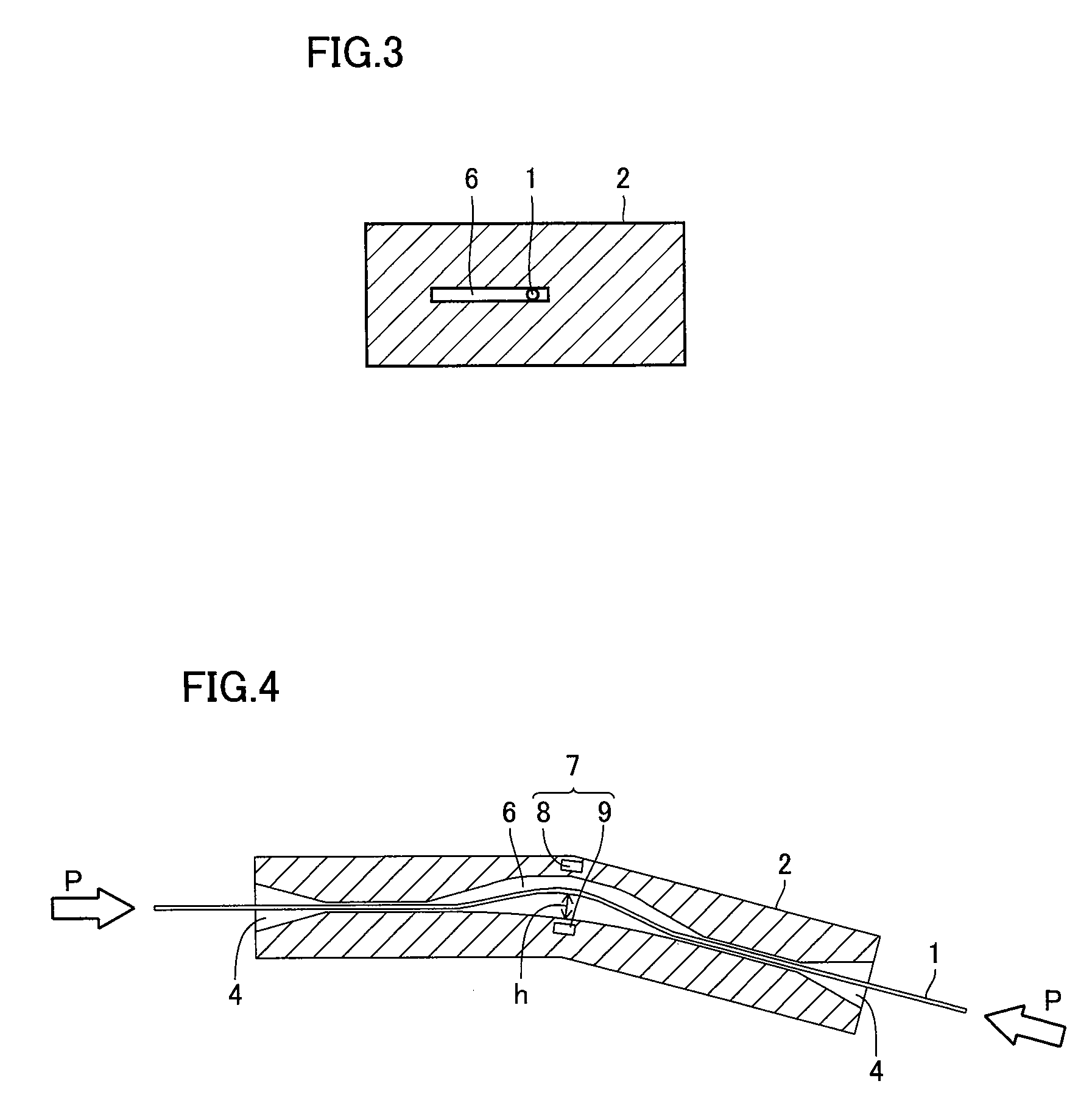
[0064]FIG. 2 is a cross-sectional schematic diagram showing an internal structure of the main body of the measurement device shown in FIG. 1. FIG. 3 is a cross-sectional view showing a cross-section along the line III-III in FIG. 1. In FIG. 2, at an inlet and an outlet of through hole 3, a tapered input / output port 4 is formed in order to facilitate insertion, by making greater the inlet and the outlet where linear body 1 passes. In a restraint portion 5 within measurement device main body 2, a diameter of through hole 3 is slightly greater than a diameter of linear body 1 (for example, 105% to 120% of the diameter o...

embodiment 2

[0083]FIG. 12 is a schematic diagram showing an overall configuration of a measurement device according to Embodiment 2 representing one embodiment of the present invention. FIG. 13 is a cross-sectional schematic diagram showing an internal structure of a main body of the measurement device shown in FIG. 12. The measurement device in Embodiment 2 is basically configured in a manner similar to the measurement device in Embodiment 1 described above. Embodiment 2, however, is different from Embodiment 1 in that the sensor is configured as shown in FIG. 12.

[0084]Specifically, in FIG. 12, a measurement device 202 includes an optical sensor 32 instead of sensor 7. Optical sensor 32 includes a light source 29 emitting light and a light receiver 30 receiving light emitted by light source 29. Light receiver 30 is a line sensor representing a one-dimensional optical array sensor, that has a plurality of light-receiving elements receiving light arranged in line. In FIG. 13, light receiver 30 i...

embodiment 3

[0086]FIG. 14 is a cross-sectional schematic diagram showing an internal structure of a main body of a measurement device according to Embodiment 3 representing one embodiment of the present invention. A measurement device 203 in Embodiment 3 is basically configured in a manner similar to the measurement device in Embodiment 2 described above. Embodiment 3, however, is different from Embodiment 2 in that light receiver 30 is arranged as shown in FIG. 14. Specifically, in FIG. 14, the line sensor serving as light receiver 30 is arranged on an extension of one restraint portion 5 in space 6 of through hole 3 curving between two restraint portions 5. Namely, not-shown light source 29 and light receiver 30 are arranged to be opposed to each other with linear body 1 lying therebetween, across space 6 formed between two restraint portions 5, and arranged along a direction in which through hole 3 extends in one restraint portion 5.

[0087]An operation of the measurement device in Embodiment ...


PUM

PropertyMeasurementUnit
diameteraaaaaaaaaa
compressive forceaaaaaaaaaa
flexibilityaaaaaaaaaa

Abstract

A measurement device can detect a degree of bending of a linear body with a sensor when compressive force in a direction of longitudinal axis is applied to the linear body as a result of contact of a tip end of the linear body with an obstacle. Then, the detected degree of bending of the linear body is converted to compressive force in the direction of longitudinal axis applied to the linear body based on predetermined correlation between the degree of bending and the compressive force, so that presence of an obstacle in a direction of travel of the linear body can be sensed based on increase in the compressive force. In addition, as the same measurement device is applicable to linear bodies of various shapes and materials, cost effectiveness is achieved.

Description

RELATED APPLICATIONS[0001]This application is the U.S. National Phase under 35 U.S.C. §371 of International Application No. PCT / JP2007 / 055527, filed on Mar. 19, 2007, which in turn claims the benefit of Japanese Application No. 2006-085317, filed on Mar. 27, 2006 and Japanese Application No. 2006-183495, filed on Jul. 3, 2006, the disclosures of which Applications are incorporated by reference herein.TECHNICAL FIELD[0002]The present invention relates to a measurement device and a measurement method and particularly to a device and a method for measuring compressive force applied to a linear body having flexibility.BACKGROUND ART[0003]A linear body having flexibility has been put into practical use as a linear medical appliance inserted in a vessel in a body. For example, a guide wire or a catheter inserted in a vessel in a body such as a blood vessel, a ureter, a bronchus, an alimentary canal, or a lymph vessel, or a wire having an embolus coil attached at a tip end for embolizing a...

Claims


Application Information

Patent Timeline
Patent Type & Authority Patents(United States)
IPC IPC(8): G01L1/12G01L1/24
CPCG01L1/24A61B5/6885
Inventor FUJIMOTOSANONAGANO, YOSHITAKA
Owner NAGOYA INSTITUTE OF TECHNOLOGY
Why Eureka
Try Eureka