
Circuit protection system

a protection system and circuit protection technology, applied in the integration of power network operation systems, data switching networks, generating/distributing signals, etc., can solve problems such as increasing the risk of system damage, ignoring the state, topology or configuration of the power distribution system of the current system, and applying incorrect algorithms and unwanted functions of power control devices

Active Publication Date: 2011-07-26
ABB (SCHWEIZ) AG
View PDF5 Cites 18 Cited by
  • Summary
  • Abstract
  • Description
  • Claims
  • Application Information

AI Technical Summary

Benefits of technology

The patent describes a method and system for protecting a circuit with power switching devices. The method involves defining the characteristics of a protection zone and creating a protection matrix based on those characteristics. The protection matrix is then used to perform a protective function on the circuit. The system includes a control processing unit that performs the protective function based on the characteristics of the protection zone. The technical effect of this patent is to provide a more effective and efficient way to protect circuits with power switching devices.

Problems solved by technology

Such a contemporary system fails to account for changes to the state, topology or configuration of the power distribution system, such as power flow changes resulting from the opening or closing of circuit breakers.
The failure of the protection system to adapt to the dynamics of the state of the power distribution system results in the application of incorrect algorithms and unwanted functions of power control devices based upon the erroneous, static state within the zone of protection.
This increases the risk of damage to the system, such as failure to timely clear a fault.
This also decreases the efficiency of the system, such as through untimely opening of circuit breakers and nuisance tripping, and can increase the extent and duration of electrical service interruption in the event of a fault.

Method used


Image

  • Circuit protection system
  • Circuit protection system
  • Circuit protection system

Examples


Embodiment Construction

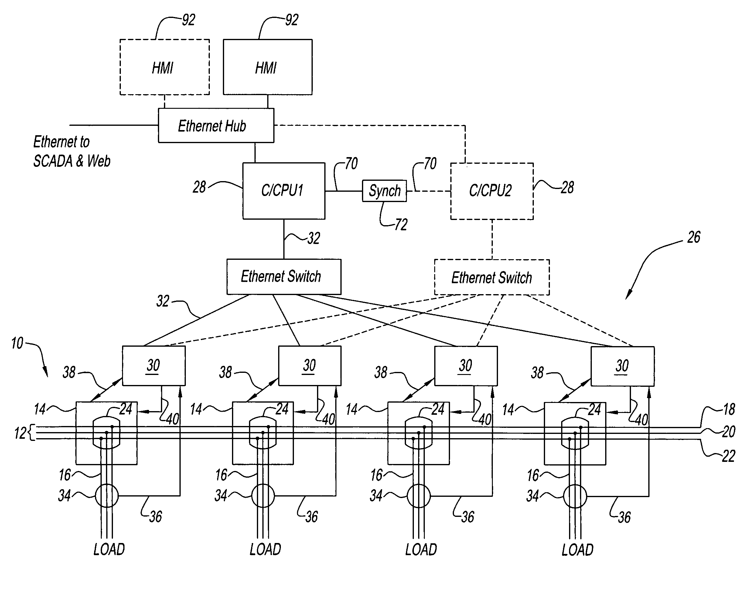
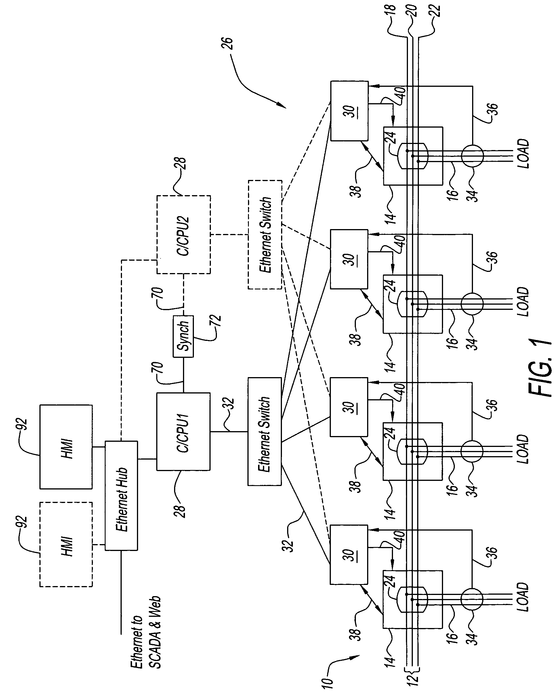
Referring now to the drawings and in particular to FIG. 1, an exemplary embodiment of a power distribution system generally referred to by reference numeral 10 is illustrated. System 10 distributes power from at least one power bus 12 through a number or plurality of power switching devices or circuit breakers 14 to branch circuits 16.

Power bus 12 is illustrated by way of example as a three-phase power system having a first phase 18, a second phase 20, and a third phase 22. Power bus 12 can also include a neutral phase (not shown). System 10 is illustrated for purposes of clarity distributing power from power bus 12 to four circuits 16 by four breakers 14. Of course, it is contemplated by the present disclosure for power bus 12 to have any desired number of phases and / or for system 10 to have any desired number of circuit breakers 14 and any topology of circuit breakers, e.g., in series, or in parallel, or other combinations.

Each circuit breaker 14 has a set of separable contacts 24...


PUM


Abstract

A circuit protection system is provided that utilizes a single state definition for each of the zones of protection of the circuit to increase computational efficiency. Multiple zone protective functions can be performed on a single zone of protection and can reference the single state definition.

Description

BACKGROUND OF THE INVENTION1. Field of the InventionThis disclosure relates generally to power distribution systems and more particularly, to a method and apparatus for a circuit protection system providing multiple zone protective functions for zone protection throughout the system.2. Description of the Prior ArtIn power distribution systems, power is distributed to various loads and is typically divided into branch circuits, which supply power to specified loads. The branch circuits can also be connected to other power distribution equipment.Due to the concern of an abnormal power condition in the system, i.e., a fault, it is known to provide circuit protective devices or power switching devices, e.g., circuit breakers, to protect the circuit. The circuit breakers seek to prevent or minimize damage and typically function automatically. The circuit breakers also seek to minimize the extent and duration of electrical service interruption in the event of a fault.It is further known t...

Claims


Application Information

Patent Timeline
Patent Type & Authority Patents(United States)
IPC IPC(8): H02H3/00G06F1/12H02H1/00H02H3/05H02J13/00H04L12/24
CPCG06F1/12H02H7/261H02J13/0062H02J13/0079H02J13/0086H02H3/006H02H3/05H02J3/005Y04S20/224H02J2003/001H02J2003/146Y02B70/3216Y04S20/221H02J13/0072H02J2310/64H02J13/00018H02J2310/12H02J13/00016H02J13/00004H02J13/0004Y02B70/30Y04S20/222Y04S50/10Y02B70/3225H02J3/007H02J3/0012
Inventor PAPALLO, THOMAS F.LAVOIE, GREGORY P.VANDEVANTER, JOHN S.
Owner ABB (SCHWEIZ) AG
Learn More