Steering column assembly having rollers to reduce friction during column collapse

a technology of steering column and roller, which is applied in the direction of steering parts, vehicle components, transportation and packaging, etc., can solve the problems of high sliding friction load during steering column collapse, high friction load of shaft and compression bracket, undesirably high column collapse load, etc., to prevent sliding frictional engagement, reduce rolling coefficient of friction, and prevent high sliding frictional load

Inactive Publication Date: 2011-08-02
GM GLOBAL TECH OPERATIONS LLC +1
View PDF4 Cites 4 Cited by
  • Summary
  • Abstract
  • Description
  • Claims
  • Application Information

AI Technical Summary

Benefits of technology

[0008]Accordingly, the subject invention includes a roller supported on and rotatable about the shaft. The roller engages the planar wall in rolling engagement therewith, and positions the shaft within the telescope slot to prevent sliding frictional engagement between the shaft and the sidewall during longitudinal movement of the column jacket, thereby preventing production of a high sliding frictional load during collapse of the steering column assembly. The rolling engagement between the roller and the planar wall produces a lower rolling coefficient of friction than the high sliding frictional engagement. Therefore, the steering column assembly of the subject invention reduces the frictional load and a resultant steering column overturning force produced during collapse of the steering column assembly.

Problems solved by technology

When the column is under the collapsing loads, the sliding frictional engagement between the shaft and the compression bracket produce a high friction load.
This high friction load leads to an undesirably high column-collapsing load.
Further, certain vans and other vehicles having a relatively high angle of steering column orientation may have high overturning moments exerted on the column during crash that may induce high sliding friction loads during steering column collapse.

Method used


Image

  • Steering column assembly having rollers to reduce friction during column collapse
  • Steering column assembly having rollers to reduce friction during column collapse
  • Steering column assembly having rollers to reduce friction during column collapse

Examples


Embodiment Construction

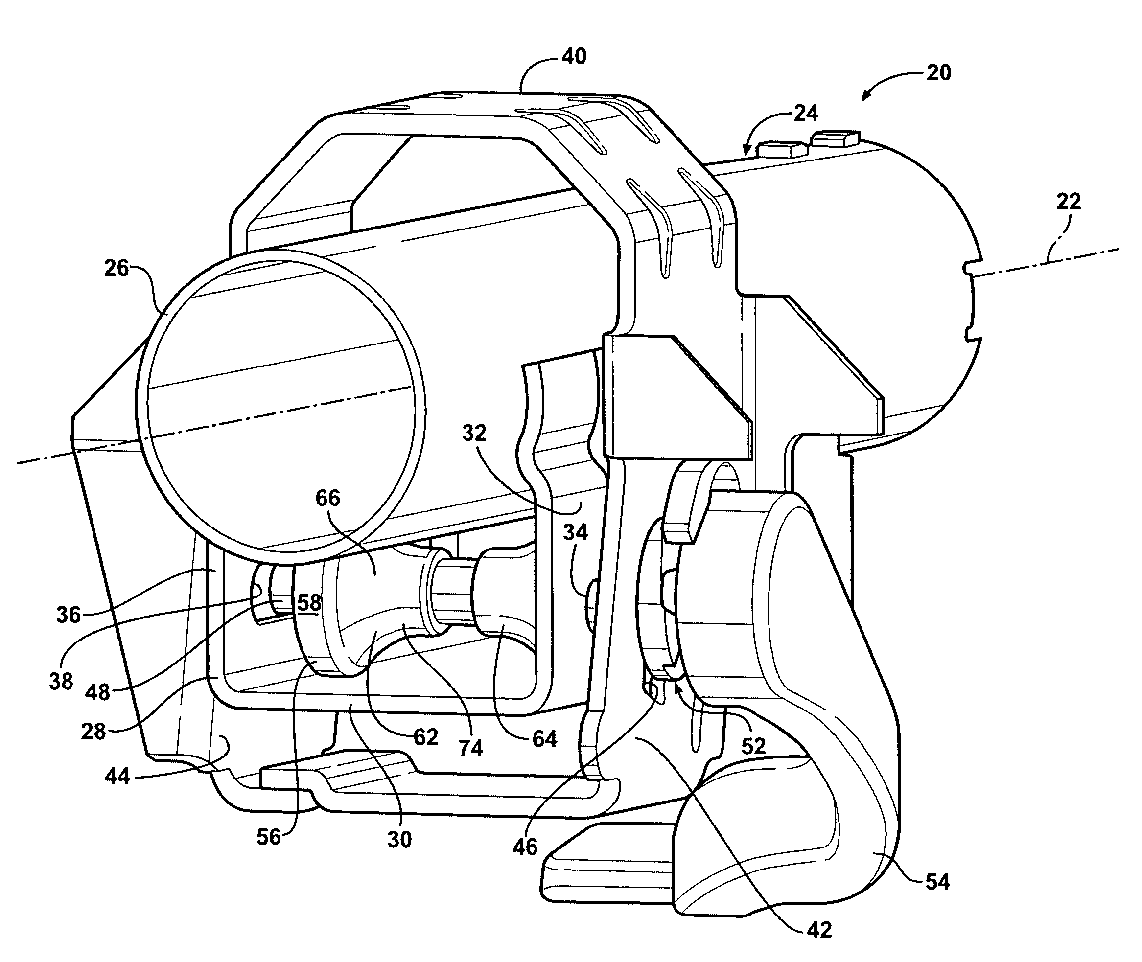
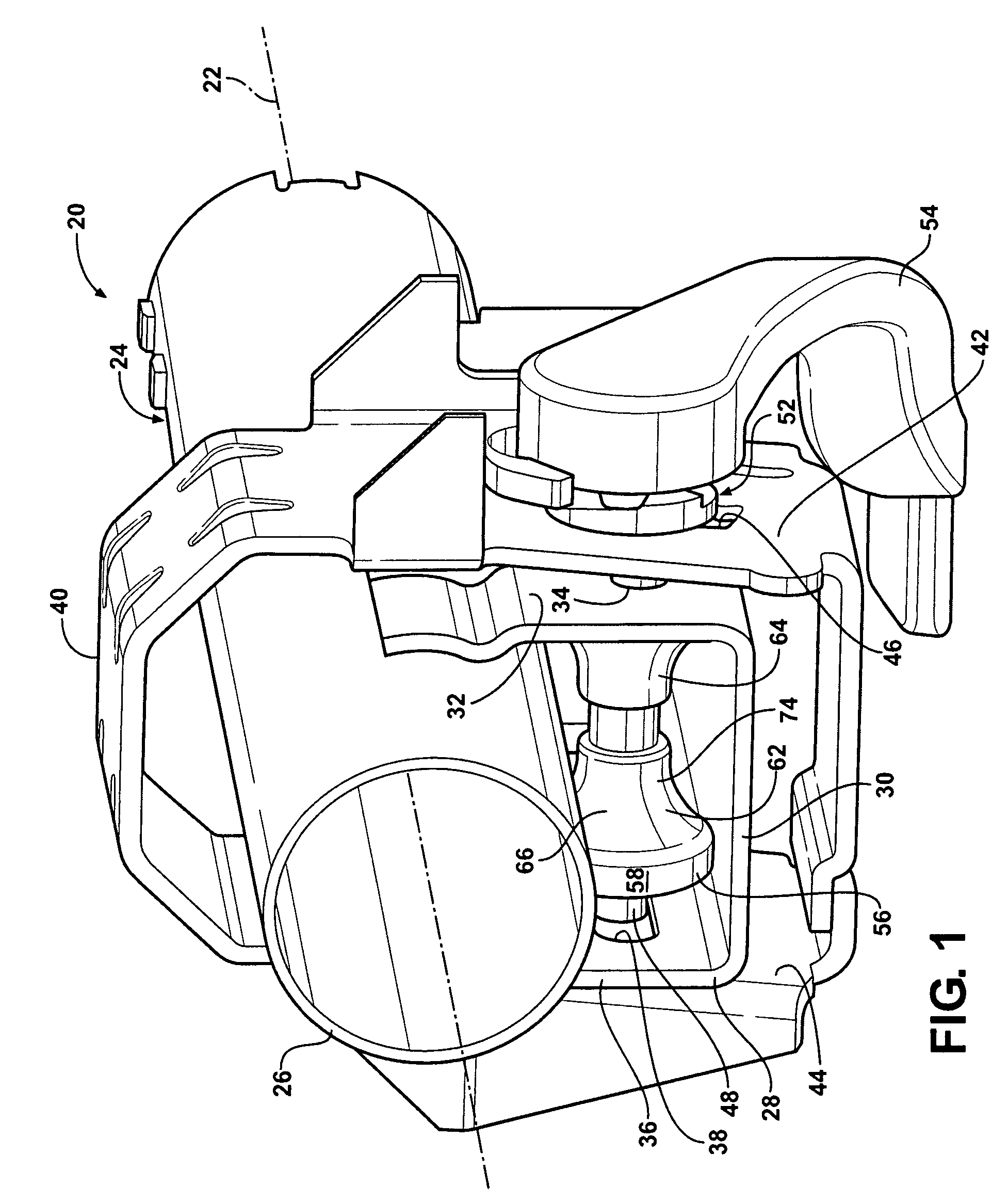
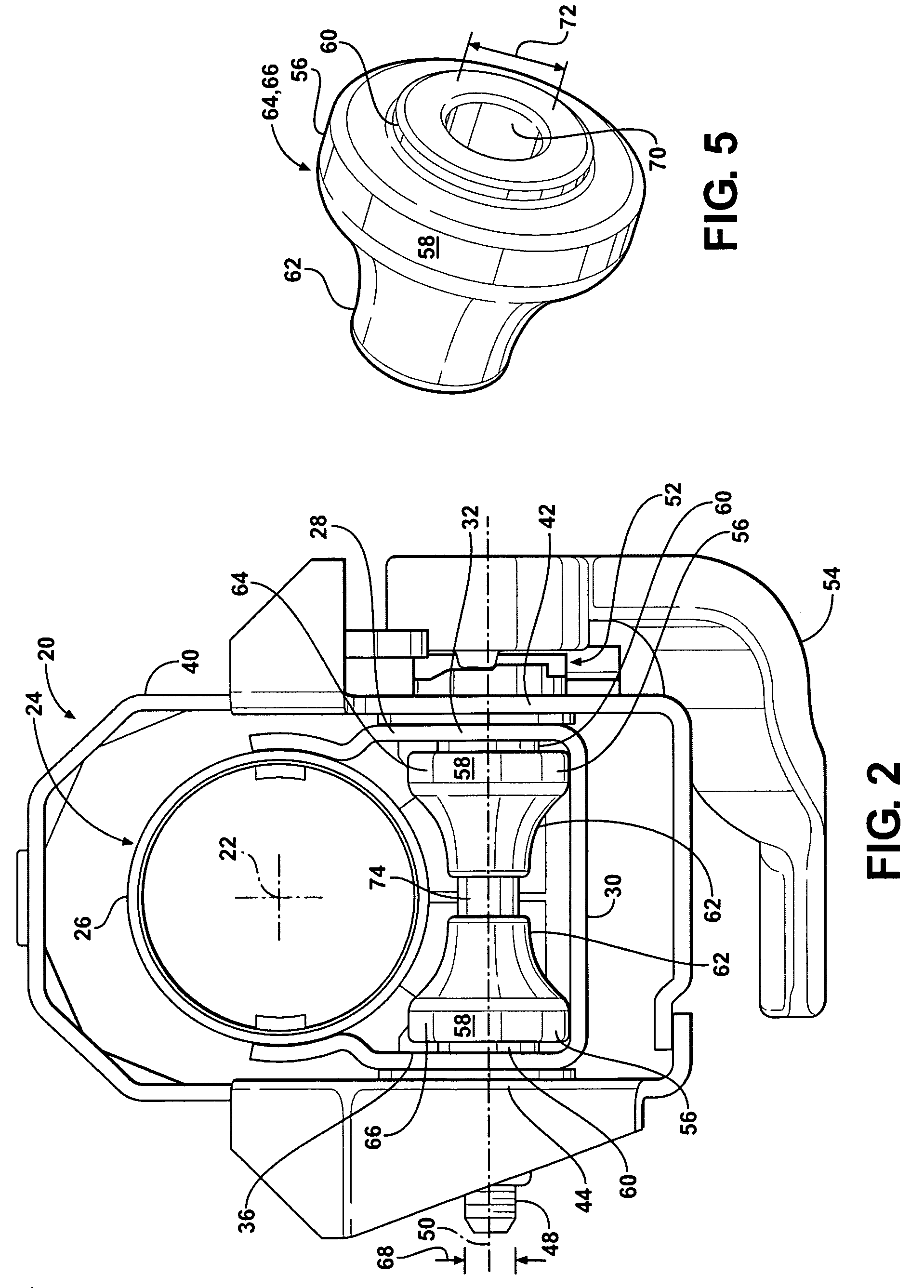
[0015]Referring to the Figures, wherein like numerals indicate corresponding parts throughout the several views, a steering column assembly is shown generally at 20. The steering column assembly 20 is for a vehicle and extends along a longitudinal axis 22. The steering column assembly 20 is adjustable in a telescope direction parallel to the longitudinal axis 22, i.e., the steering column assembly 20 is axially adjustable along the longitudinal axis 22.

[0016]Referring to FIGS. 1 and 2, the steering column assembly 20 includes a column jacket 24. The column jacket 24 extends along the longitudinal axis 22. The column jacket 24 includes a jacket portion 26 and a compression bracket 28. The compression bracket 28 is fixedly attached to the jacket portion 26. The compression bracket 28 includes a planar wall 30 spaced from the jacket portion 26, and at least one sidewall 32, 36 extending between the planar wall 30 and the jacket portion 26.

[0017]Referring also to FIGS. 3 and 4, the at l...


PUM


Abstract

A steering column assembly includes a column jacket having a jacket portion and a compression bracket attached thereto. The compression bracket includes a planar wall spaced from the column portion and a sidewall extending between the planar wall and the jacket portion. The sidewall defines a telescope slot extending along a longitudinal axis. A shaft extends through the telescope slot of the sidewall. A roller is supported on and rotatable about the shaft, and in rolling engagement with the planar wall. The roller positions the shaft within the telescope slot to prevent sliding frictional engagement between the shaft and the sidewall. The rolling coefficient of friction between the roller and the planar wall is less than the sliding coefficient of friction between the shaft and the sidewall to reduce a frictional load produced during longitudinal collapse of the steering column assembly.

Description

CROSS REFERENCE TO RELATED APPLICATION[0001]This application claims the benefit of U.S. Provisional Patent Application Ser. No. 61 / 010,335, filed on Jan. 8, 2008, the disclosure of which is hereby incorporated by reference.BACKGROUND OF THE INVENTION[0002]1. Field of the Invention[0003]The subject invention relates to a steering column assembly for a vehicle. More specifically, the subject invention relates to a telescopically adjustable steering column assembly adjustable along a longitudinal axis, which is also collapsible along the longitudinal axis in response to a collision event.[0004]2. Description of the Prior Art[0005]Many telescopically adjustable steering column assemblies include a compression bracket coupled to a column jacket that is longitudinally moveable along a longitudinal axis. Typically, the compression bracket defines a telescope slot through which a shaft, e.g., a rake bolt, extends. The column jacket moves relative to the shaft along the longitudinal axis wit...

Claims


Application Information

Patent Timeline
Patent Type & Authority Patents(United States)
IPC IPC(8): B62D1/00
CPCB62D1/185B62D1/192
Inventor GERZSENY, KEVIN D.DOUPONCE, MICHAEL D.REIDER, STEPHEN J.DOLLOFF, RICK B.RIEFE, RICHARD K.
Owner GM GLOBAL TECH OPERATIONS LLC
Why Eureka
Try Eureka