LED illuminating device and lamp unit thereof
a technology of led illuminating device and lamp unit, which is applied in the direction of lighting support device, fixed installation, lighting and heating apparatus, etc., can solve the problem that the illuminating device cannot obtain the desired illumination area
- Summary
- Abstract
- Description
- Claims
- Application Information
AI Technical Summary
Benefits of technology
Problems solved by technology
Method used
Image
Examples
first embodiment
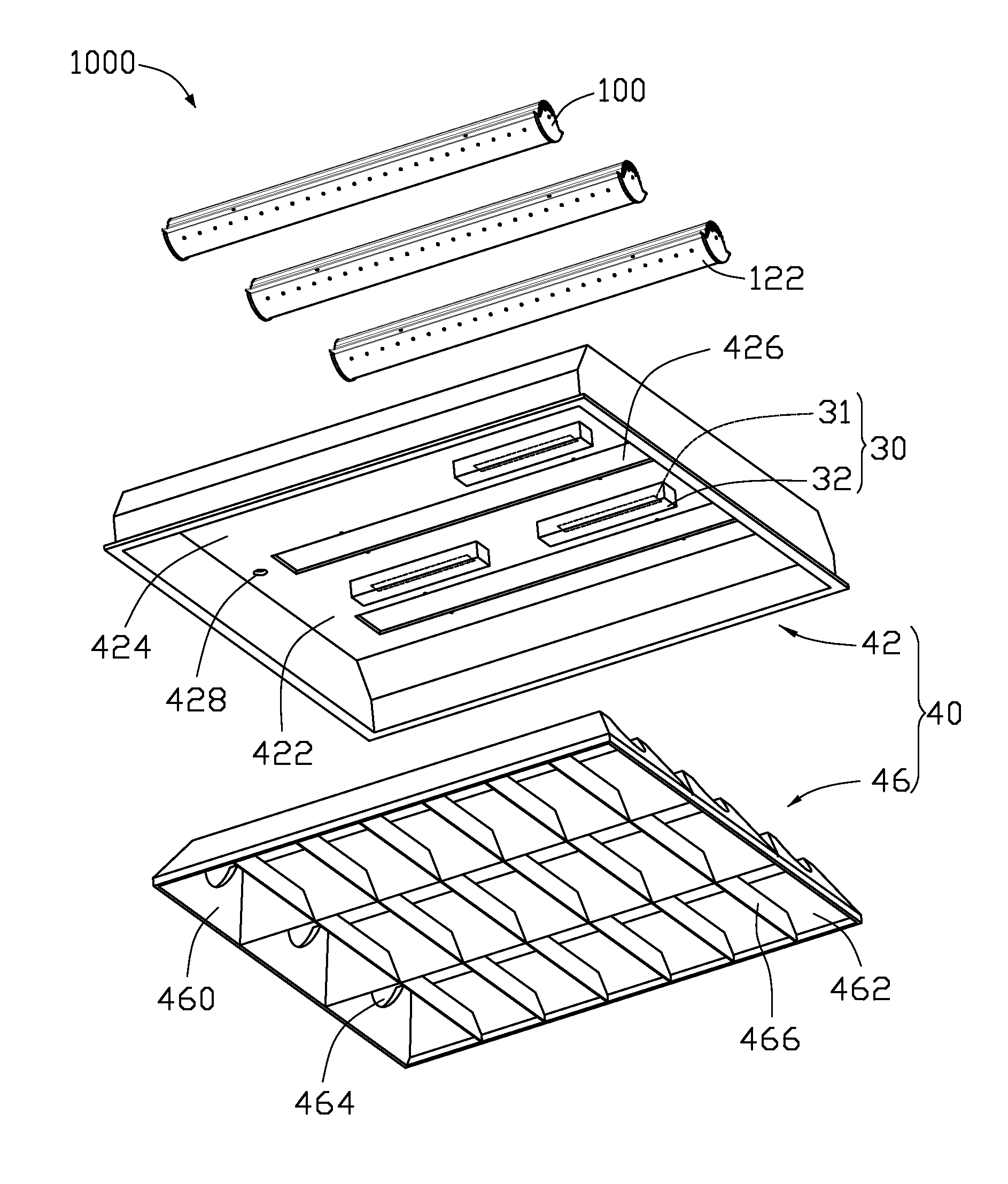
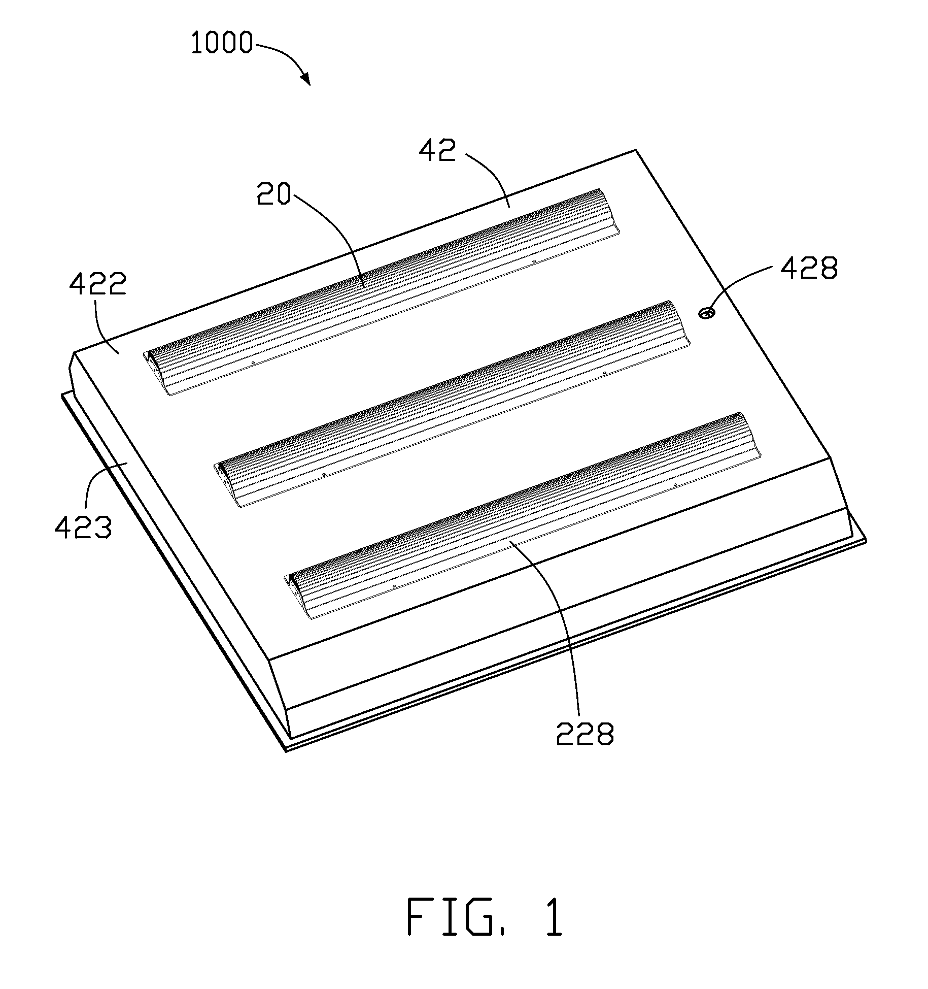
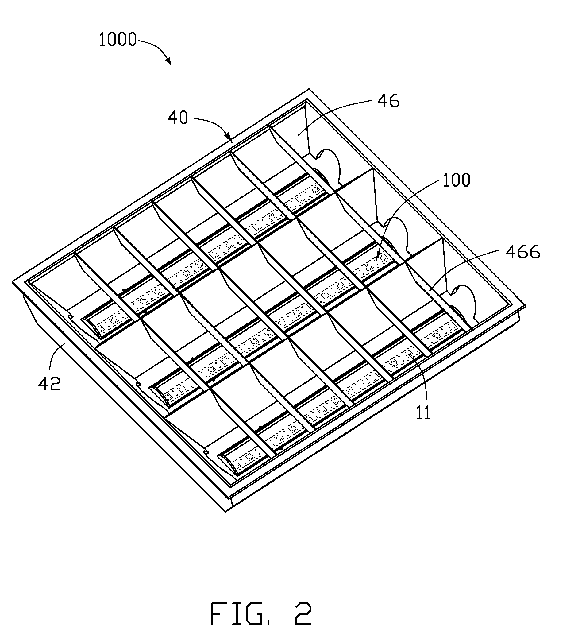
[0019]Referring to FIGS. 1-3, an LED illuminating device 1000 includes a mounting module 40, a plurality of lamp units 100 and an electrical module 30 mounted on the mounting module 40. The lamp units 100 are identical to each other, and are arranged parallel to each other.
[0020]Referring to FIGS. 4-6, the lamp unit 100 includes a light-emitting module 10 and a heat sink 20 arranged above the light-emitting module 10. The light-emitting module 10 is electrically connected with the electrical module 30.
[0021]The heat sink 20 includes an elongated metal base 22 and a plurality of metal fins 24 extending from the base 22. A transverse cross section of the base 22 is substantially of an isosceles trapezoid with an isosceles trapezoid-shaped recess 26 in a bottom side thereof along a longitudinal direction of the base 22, to thereby form an outer convex surface 223 at a top side thereof, and an opposite inner U-shaped concave surface 261 at a bottom side thereof. The convex surface 223 ...
second embodiment
[0034]Referring to FIG. 7, a lamp unit 100a of an LED illuminating device is illustrated. Except the following differences, the lamp unit 100a of the present embodiment is essentially the same as the lamp unit 100 of the previous embodiment. In the present embodiment, a base 22a of a heat sink of the lamp unit 100a defines longitudinally an elongated groove 227 in a horizontal first plane 262a thereof. Light source 11a is received in an elongated recess 26a defined in the base 22a and attached to the first plane 262a. A flat heat pipe 50 is received in the groove 227 and sandwiched between the base 22a and the light source 11a to transfer heat of the light source 11a to the base 22a. The heat pipe 50 is well known for heat dissipation due to its excellent heat transfer performance. The heat pipe 50 has a low thermal resistance in heat transfer due to a phase change mechanism of working fluid employed in the heat pipe 50, which improves the heat conduction efficiency between the lig...
third embodiment
[0035]Referring to FIG. 8, a lamp unit 100b of an LED illuminating device is illustrated. Except the following differences, the lamp unit 100b of the present embodiment is essentially the same as the lamp unit 100 of the previous embodiment. In the present embodiment, a base 22b of a heat sink of the lamp unit 100b forms a substantially V-shaped concave surface 261b at a bottom side thereof. The concave surface 261b includes two sloping planes 264b intersecting with each other. The light source 11b includes a pair of light bars received in an elongated recess 26b defined in the base 22b and symmetrically attached to the two sloping planes 264b. Each of the two sloping planes 264b of the concave surface 261b of the base 22b functions as a heat-absorbing surface for the light source 11b. The base 22b defines a plurality of exchanging holes 222b through the base 22b at a joint of the two sloping planes 264b of the concave surface 261b.
PUM
 Abstract
Description
Claims
Application Information
 - R&D
- Intellectual Property
- Life Sciences
- Materials
- Tech Scout
- Unparalleled Data Quality
- Higher Quality Content
- 60% Fewer Hallucinations
Browse by: Latest US Patents, China's latest patents, Technical Efficacy Thesaurus, Application Domain, Technology Topic, Popular Technical Reports.
© 2025 PatSnap. All rights reserved.Legal|Privacy policy|Modern Slavery Act Transparency Statement|Sitemap|About US| Contact US: help@patsnap.com


