Compressor ported shroud for foil bearing cooling

a compression shaft and foil bearing technology, applied in the field of gas lubricated bearings, can solve the problems of loss of wearability of foil bearing coatings, reduced cooling oil supply, and reduced wear resistance of bearings

Active Publication Date: 2011-08-02
HONEYWELL INT INC
View PDF17 Cites 24 Cited by
  • Summary
  • Abstract
  • Description
  • Claims
  • Application Information

AI Technical Summary

Problems solved by technology

However, this supply of cooling oil ceases when the engine stops, and the residual heat in the turbine rotor can be sufficient to damage the bearings adjacent the turbine rotor.
Such bearings are especially vulnerable to the effect of heat-soak in the case of a gas turbine engine having a regenerative heat-exchanger and a thermally insulated main casing, because the residual heat in the turbine rotor on shutdown is virtually prevented from being dissipated to the atmosphere.
If the temperature exceeds acceptable limits, there may be a loss of wearability of foil bearing coatings or, in the extreme case, evaporation and destruction of the coating.
Similarly, the foil material may creep if the temperature is too high, with attendant loss of elasticity and load bearing capacity.
However, the Wieland patent does not disclose any criteria for assigning a location for the point in the compressor where bleed air may be drawn from the compressor.
Additionally, the Wieland patent does not disclose any relationship between the size of the bleed hole through which the air is bled and the size of other chambers within the engine.

Method used


Image

  • Compressor ported shroud for foil bearing cooling
  • Compressor ported shroud for foil bearing cooling
  • Compressor ported shroud for foil bearing cooling

Examples


Embodiment Construction

[0020]The following detailed description is of the best currently contemplated modes of carrying out the invention. The description is not to be taken in a limiting sense, but is made merely for the purpose of illustrating the general principles of the invention, since the scope of the invention is best defined by the appended claims.

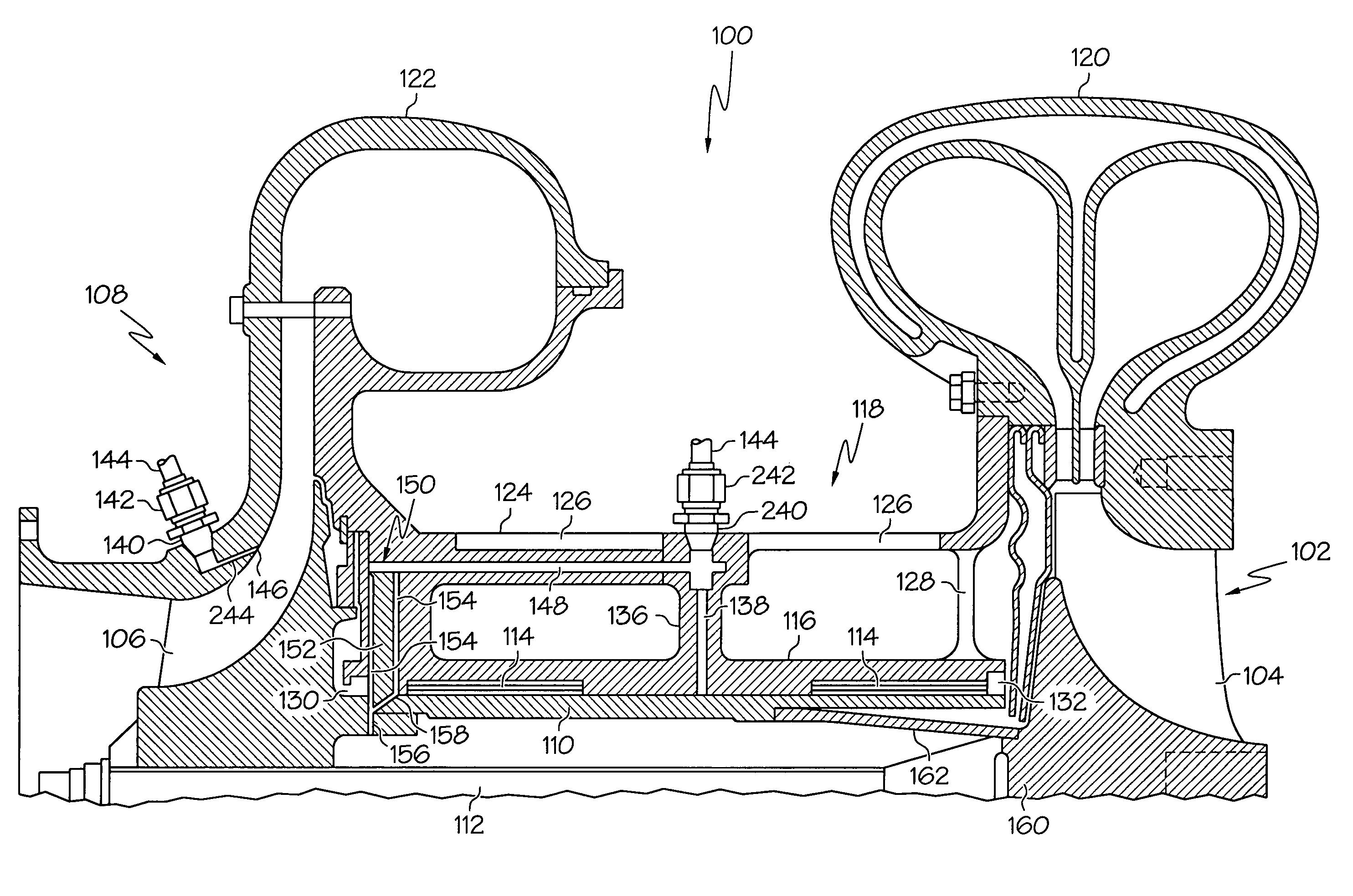
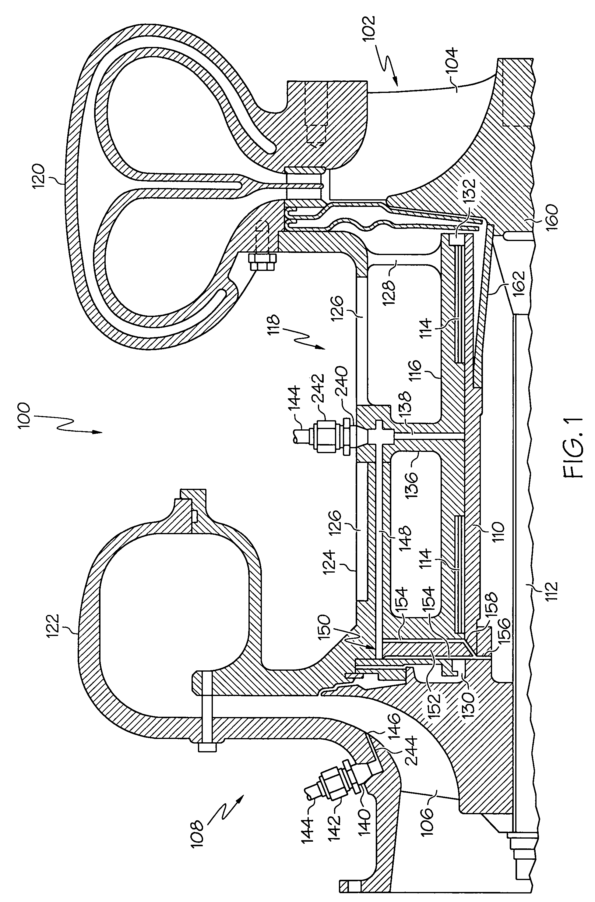
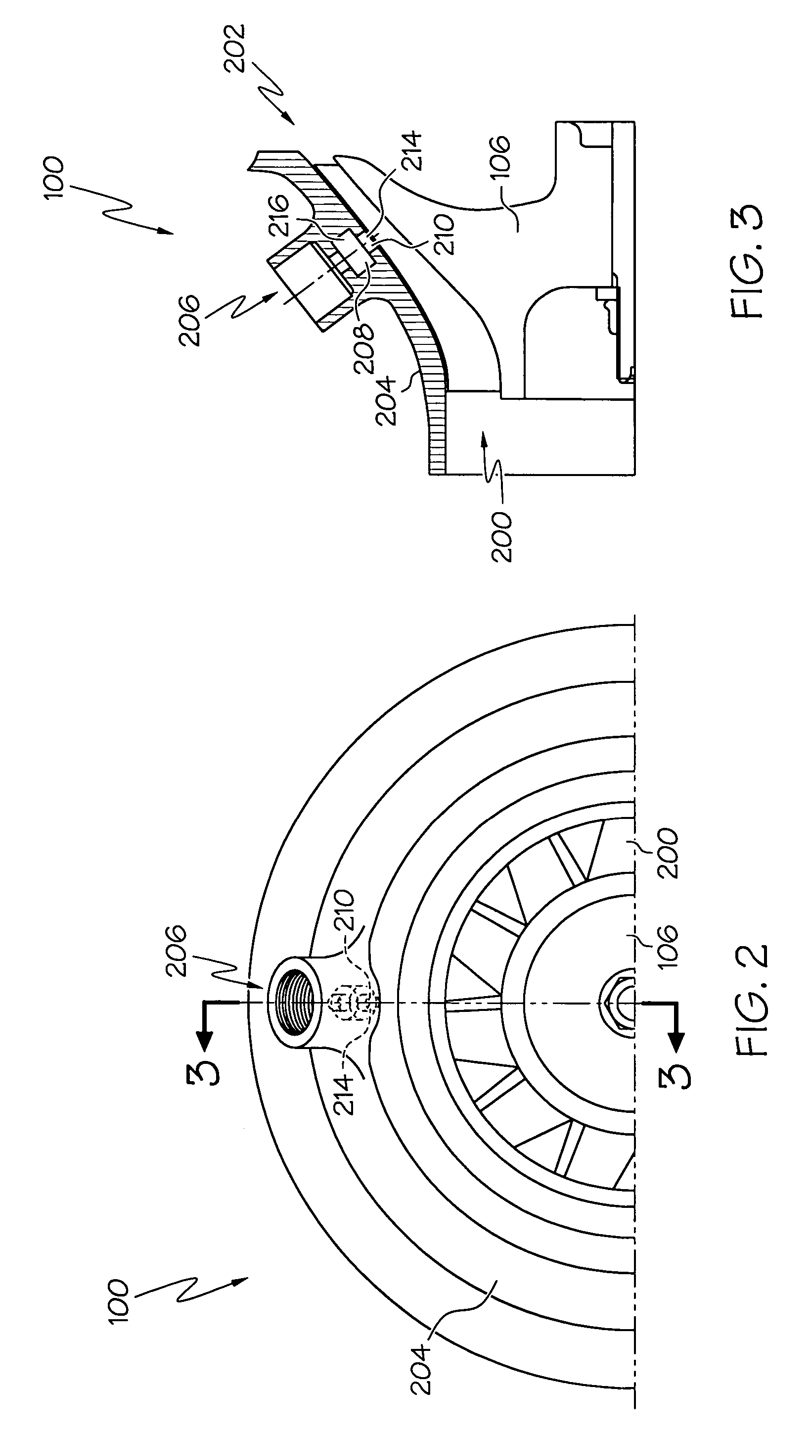
[0021]Broadly, the present invention generally provides an apparatus and method for cooling bearings in gas turbines. The present invention may also be used to cool an integral motor (such as a compressor, turbine, and motor integral on the same shaft). The cooling apparatus produced according to the present invention may find beneficial use in many industries including aerospace and industrial applications. The cooling apparatus of the present invention may be beneficial in applications including electricity generation, naval propulsion, pumping sets for gas and oil transmission, aircraft propulsion, automobile engines, and stationary power plants. Thi...


PUM


Abstract

A compressor ported shroud takes compressed air from the shroud of the compressor before it is completely compressed and delivers it to foil bearings. The compressed air has a lower pressure and temperature than compressed outlet air. The lower temperature of the air means that less air needs to be bled off from the compressor to cool the foil bearings. This increases the overall system efficiency due to the reduced mass flow requirements of the lower temperature air. By taking the air at a lower pressure, less work is lost compressing the bearing cooling air.

Description

GOVERNMENT RIGHTS[0001]This invention was made with the support of the United States Government under Contract DE-FC04-02-AL67624 awarded by the Department of Energy under its PEM Fuel Cell Turbo-Compressor Program. The Government may have certain rights to this invention.BACKGROUND OF THE INVENTION[0002]The present invention generally relates to gas lubricated bearings associated with the rotating shafts of gas turbines, turbochargers, and turbocompressors, and more specifically, to an apparatus and method for cooling such bearings by dissipating heat from the bearings.[0003]In gas turbine engines, or any other machinery in which high temperature rotors are situated adjacent to high speed bearings, it is essential to maintain the bearings at an acceptably low temperature. This is normally achieved, when the engine is running, by providing the bearings with an adequate supply of lubricating oil from a pump driven by the engine or an external motor driven pump. However, this supply o...

Claims


Application Information

Patent Timeline
Patent Type & Authority Patents(United States)
IPC IPC(8): F03B11/06F01D25/16
CPCF01D25/125F01D25/22F04D29/057F04D29/063F04D25/024F16C37/00F04D29/584F05D2220/40F16C2360/24F04D29/4206F16C37/002
Inventor ELPERN, DAVID G.MCCABE, NIALLGEE, MARK
Owner HONEYWELL INT INC
Why Eureka
Try Eureka