
Graft fixation using a plug against suture

a technology of suture and plug, which is applied in the field of suture fixation methods and instruments, can solve the problems of affecting the sliding of the suture or graft, affecting the healing effect of the graft,

Inactive Publication Date: 2011-08-09
ARTHREX
View PDF9 Cites 206 Cited by
  • Summary
  • Abstract
  • Description
  • Claims
  • Application Information

AI Technical Summary

Benefits of technology

This solution provides a stronger fixation of the graft to the bone by allowing free sliding of sutures through the eyelet implant, facilitating precise positioning and secure attachment without damaging the surrounding tissue or bone, and eliminates the need for additional steps that could cause abrasion.

Problems solved by technology

Although the above-described technique provides an improved method of graft fixation to bone, the flexible loop configuration at the end of the driver disadvantageously impedes sliding of the suture or graft which is fed through the suture loop.
This, in turn, may abrade the adjacent tissue and / or damage the bone or cartilage.

Method used


Image

  • Graft fixation using a plug against suture
  • Graft fixation using a plug against suture
  • Graft fixation using a plug against suture

Examples


Embodiment Construction

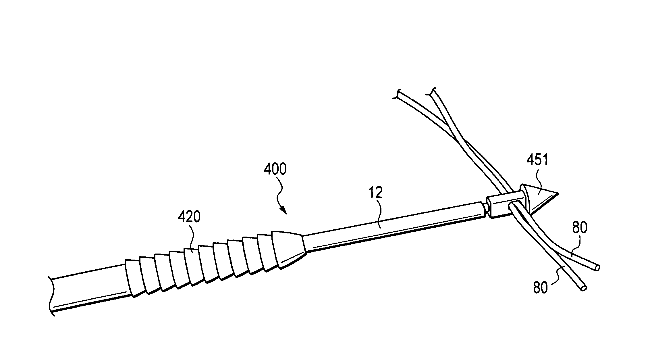
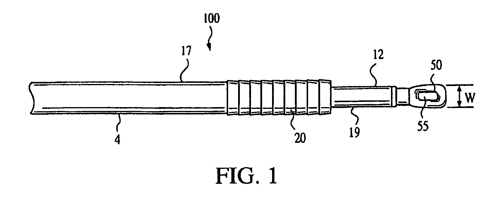
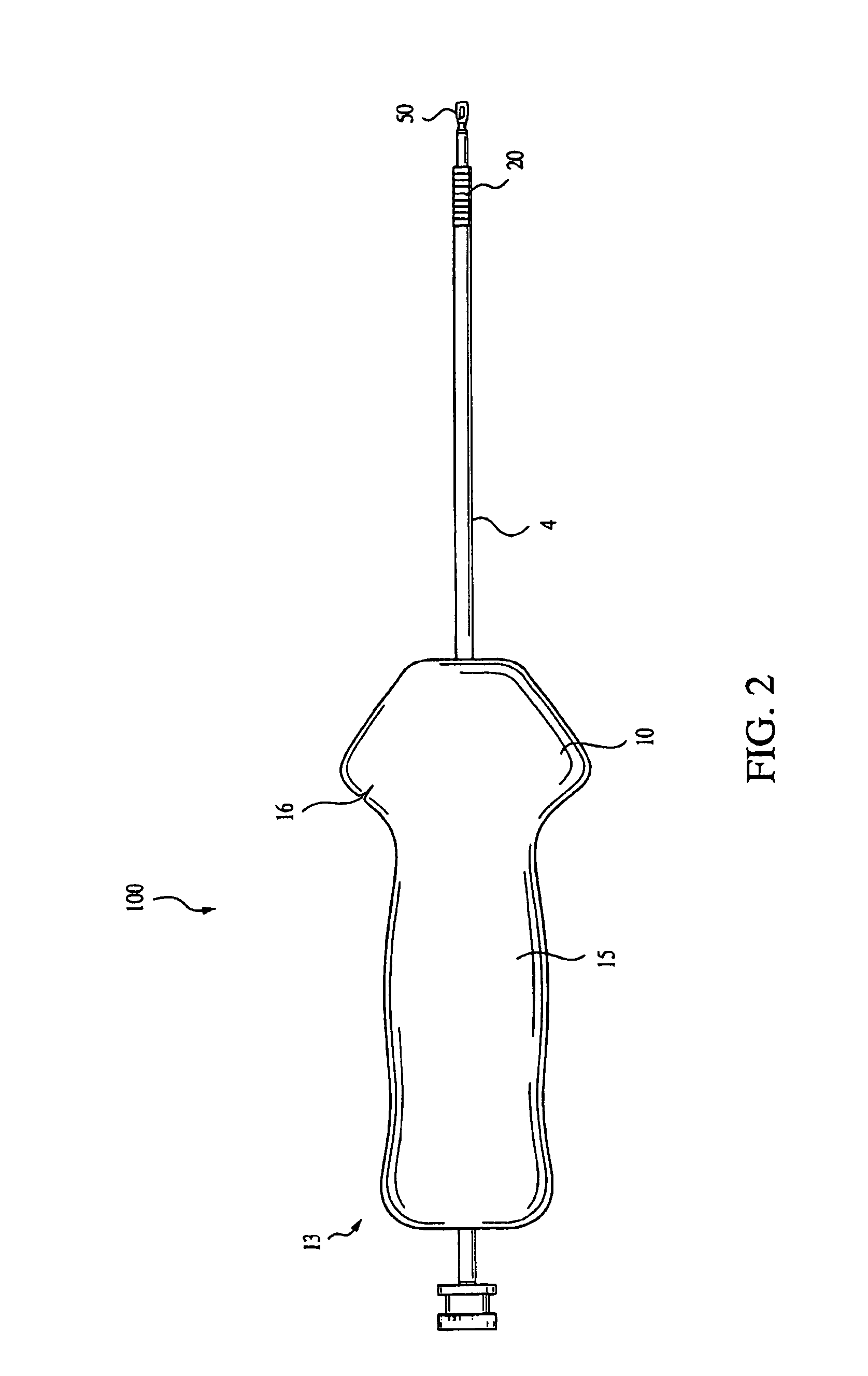
Referring now to the drawings, where like elements are designated by like reference numerals, FIGS. 1 and 2 illustrate an implant driver 100 of the present invention. Driver 100 includes a body 4, preferably in the form of a cylinder, and having a distal end 12 (FIG. 1) and a proximal end 13 (FIG. 2). The body 4 of driver 100 includes an outer shaft 17 and an inner shaft 19. The outer shaft 17 is cannulated for receiving inner shaft 19.

As illustrated in FIG. 1, driver 100 is pre-loaded with an interference device 20. Preferably, the interference device 20 is a screw or an interference plug, preferably formed of a bioabsorbable material such as PLLA. If a screw is employed, the screw may be provided with a cannulated body provided with a continuous thread having rounded outer edges. The head of the screw may be rounded to minimize abrasion or cutting of tissue. The cannulation formed through the screw is preferably hex-shaped and accepts the correspondingly shaped inner shaft 19 of d...


PUM


Abstract

A method for securing soft tissue to bone which does not require the surgeon to tie suture knots to secure the tissue to the bone. Suture is passed through the graft at desired points. A cannulated plug or screw is pre-loaded onto the distal end of a driver provided with an eyelet implant at its distal end. Suture attached to the graft is passed through the eyelet of the implant located at the distal end of the driver. The distal end of the driver together with the eyelet implant is inserted into the bone. Tension is applied to the suture to position the graft at the desired location relative to the bone. The screw or plug is advanced into the pilot hole by turning the interference screw or tapping the plug until the cannulated screw or plug securely engages and locks in the eyelet implant, so that the cannulated plug or screw with the engaged eyelet implant is flush with the bone. Once the screw or plug is fully inserted and the suture is impacted into the bone, the driver is removed and any loose ends of the sutures protruding from the anchor site are then clipped short.

Description

FIELD OF THE INVENTIONThe present invention relates to methods and instruments for fixation of sutures and tissue to bone.BACKGROUND OF THE INVENTIONWhen soft tissue such as a ligament or a tendon becomes detached from a bone, surgery is usually required to reattach or reconstruct the tissue. Often, a tissue graft is attached to the bone to facilitate regrowth and permanent attachment. Various fixation devices, including sutures, screws, staples, wedges, and plugs have been used in the past to secure soft tissue to bone. For example, in typical interference screw fixation, the graft is fixed to the bone by driving the screw into a blind hole or a tunnel in the bone while trapping the end of the graft between the screw and the bone tunnel. In other methods, the graft is simply pinned against the bone using staples or sutures tied around the end of the graft to the bone.Application Ser. No. 09 / 886,280 filed on Jun. 22, 2001, the disclosure of which is incorporated by reference herein,...

Claims


Application Information

Patent Timeline
Patent Type & Authority Patents(United States)
IPC IPC(8): A61B17/04A61B17/56
CPCA61B17/0401A61F2/0805A61F2/0811A61F2002/0888A61B17/8645A61B17/8875A61B2017/00907A61B2017/0403A61B2017/0409A61B2017/0414A61B2017/044A61B2017/0445A61B2017/0448A61B2017/045A61F2002/0835A61F2002/0852A61F2002/0858A61B17/864
Inventor DREYFUSS, PETER J.
Owner ARTHREX
Learn More