Systems and methods for formation and harvesting of nanofibrous materials

a nanofibrous material and nanotechnology, applied in the field of systems for forming and harvesting nanofibrous materials, can solve the problems of affecting the overall reaction kinetics, blocking the exit of nanomaterials from the chamber, etc., to avoid avoiding compromising the integrity of yarn, and minimizing the bonding of non-woven sheets

Active Publication Date: 2011-08-09
NANCOMP TECHNOLOGIES INC
View PDF97 Cites 65 Cited by
  • Summary
  • Abstract
  • Description
  • Claims
  • Application Information

AI Technical Summary

Benefits of technology

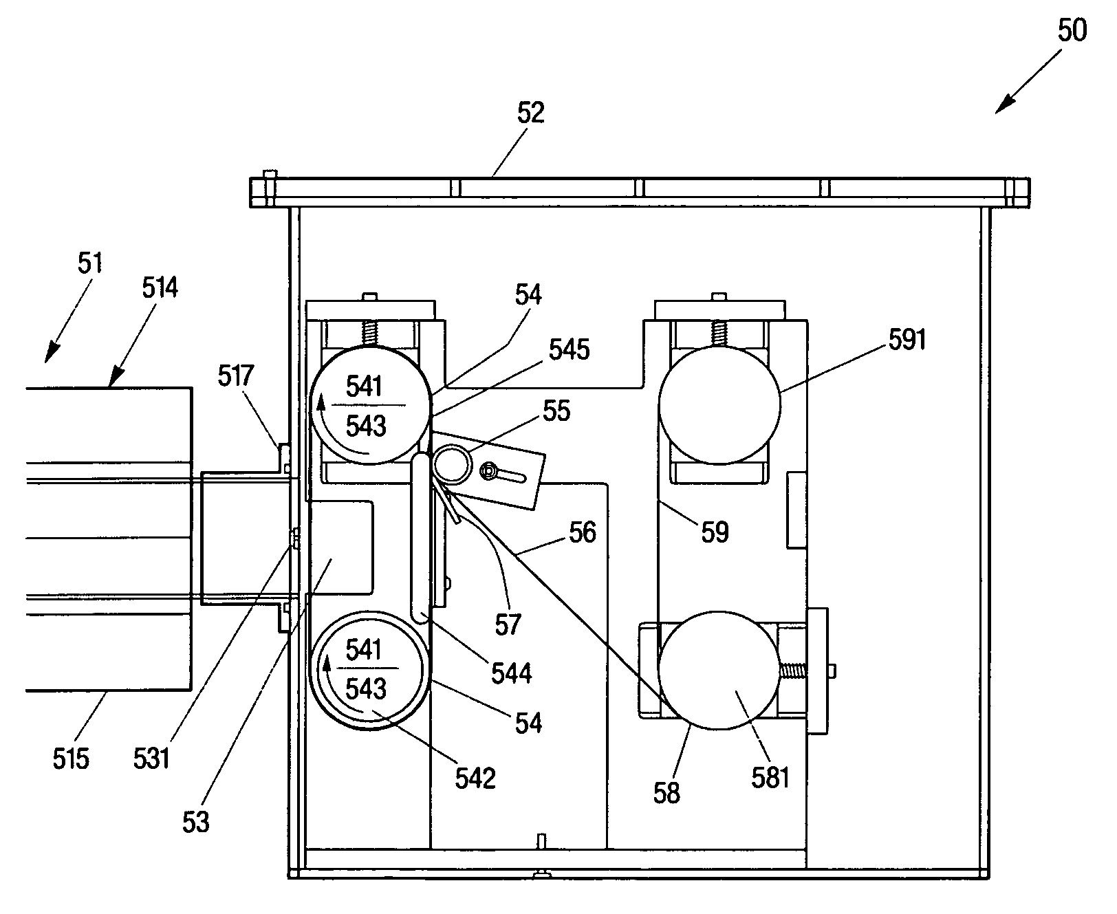
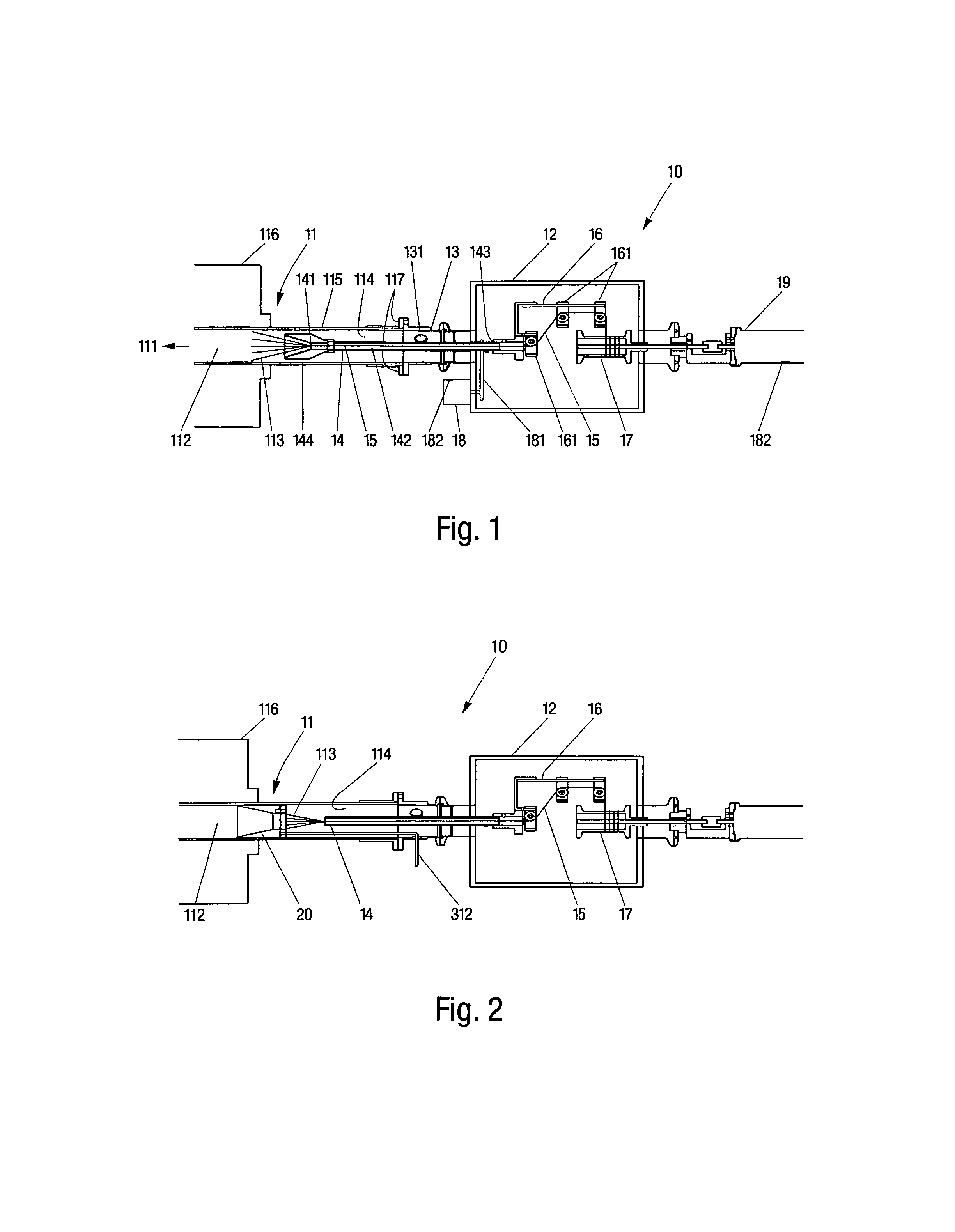
[0014]The present invention provides, in another embodiment, a system for forming a nanofibrous non-woven sheet. The system includes a housing having an inlet for engaging an independent synthesis chamber within which nanotubes may be produced. The system also includes a moving surface positioned adjacent the inlet within the housing for collecting and transporting the nanotubes flowing from the synthesis chamber. A pressure applicator may be situated adjacent the moving surface to apply a force against the collected nanotubes on the moving surface, so as to compact the nanotubes into a non-woven sheet of intermingled nanotubes. The system further includes a spool positioned within the housing and downstream of the pressure applicator for winding thereonto the non-woven sheet. A separator may also be provided to apply a material on to one side of the non-woven sheet prior to the sheet being wound about the spool to minimize bonding of the non-woven sheet to itself. The system can also include a sensor system to generate feedback data to control a rate of spin of the moving surface and spool, so as to avoid compromising the integrity of the yarn as it is being wound about the spool.
[0015]The present invention, in a further embodiment, provides a method for forming a nanofibrous yarn. The method includes receiving a plurality of synthesized nanotubes moving substantially in one direction. The environment may be an airtight environment. In an embodiment, prior to receiving, a vortex flow may be imparted on to the nanotubes so as to provide an initial twisting. Next, the nanotubes may be twisted together into a yarn in a direction substantially transverse to the direction of movement of the nanotubes. Thereafter, the yarn may be moved toward an area for harvesting and subsequently harvested by winding the yarn about an axis substantially transverse to a direction of movement of the yarn. The rate of winding may be controlled so as to avoid compromising the integrity of the yarn.
[0016]The present invention also provides an another method for forming a nanofibrous non-woven sheet. The method includes depositing a plurality of synthesized nanotubes onto a surface and subsequently transporting the nanotubes away from a point of deposition. Next, pressure may be applied onto the plurality of nanotubes against the surface, so as to compact the nanotubes into a non-woven sheet of intermingled nanotubes. The non-woven sheet may then be directed toward an area for harvesting. In an embodiment, a material may be put onto one side of the non-woven sheet to prevent the sheet from bonding to itself. The non-woven sheet may subsequently be harvested by winding the sheet about an axis substantially transverse to a direction of movement of the sheet. In an embodiment, The rate of winding may be controlled so as to avoid compromising the integrity of the non-woven sheet.

Problems solved by technology

In cases where large volumes of carbon nanotubes may be generated, however, the nanotubes may attach to the walls of a reaction chamber, resulting in the blockage of nanomaterials from exiting the chamber.
Furthermore, these blockages may induce a pressure buildup in the reaction chamber, which can result in the modification of the overall reaction kinetics.
An additional concern with nanomaterials may be that they need to be handled and processed without generating large quantities of airborne particulates, since the hazards associated with nanoscale materials are not yet well understood.

Method used


Image

  • Systems and methods for formation and harvesting of nanofibrous materials
  • Systems and methods for formation and harvesting of nanofibrous materials
  • Systems and methods for formation and harvesting of nanofibrous materials

Examples


Embodiment Construction

[0025]Nanotubes for use in connection with the present invention may be fabricated using a variety of approaches. Presently, there exist multiple processes and variations thereof for growing nanotubes. These include: (1) Chemical Vapor Deposition (CVD), a common process that can occur at near ambient or at high pressures, (2) Arc Discharge, a high temperature process that can give rise to tubes having a high degree of perfection, and (3) Laser ablation. It should be noted that although reference is made below to nanotube synthesized from carbon, other compound(s) may be used in connection with the synthesis of nanotubes for use with the present invention.

[0026]The present invention, in one embodiment, employs a CVD process or similar gas phase pyrolysis procedures well known in the industry to generate the appropriate nanotubes. In particular, since growth temperatures for CVD can be comparatively low ranging, for instance, from about 600° C. to about 1300° C., carbon nanotubes, bot...


PUM

PropertyMeasurementUnit
growth temperaturesaaaaaaaaaa
aspect ratioaaaaaaaaaa
temperatureaaaaaaaaaa

Abstract

A system that receives nanomaterials, forms nanofibrous materials therefrom, and collects these nanofibrous materials for subsequent applications. The system is coupled to a chamber that generates nanomaterials, typically carbon nanotubes produced from chemical vapor deposition, and includes a mechanism for spinning the nanotubes into yarns or tows. Alternatively, the system includes a mechanism for forming non-woven sheets from the nanotubes. The system also includes components for collecting the formed nanofibrous materials. Methods for forming and collecting the nanofibrous materials are also provided.

Description

RELATED US APPLICATION(S)[0001]The present application claims priority to U.S. Provisional Patent Application Ser. No. 60 / 703,328, filed Jul. 28, 2005 which application is hereby incorporated herein by reference.GOVERNMENT SUPPORT[0002]The invention was supported, in whole or in part, by Contract No. W911QY-06-C-0026 from the U.S. Army Soldier Systems Center (Natick, Mass.). The Government has certain rights in the invention.TECHNICAL FIELD[0003]The present invention relates to systems for formation and harvesting of nanofibrous materials, and more particularly to the formation of yarns and non-woven sheets from nanotubes, nanowires, or other filamentous structures having nanoscale dimensions.BACKGROUND ART[0004]Carbon nanotubes are known to have extraordinary tensile strength, including high strain to failure and relatively high tensile modulus. Carbon nanotubes may also be highly resistant to fatigue, radiation damage, and heat. To this end, the addition of carbon nanotubes to com...

Claims


Application Information

Patent Timeline
Patent Type & Authority Patents(United States)
IPC IPC(8): D01F9/12D01F9/127B01J19/08C01B31/02
CPCD04H1/4391D04H1/728D04H1/44D04H1/4382D01G1/06D01F9/127D04H1/74D01F9/133B82Y30/00D02G3/02D10B2101/122Y10S977/842Y10S977/742Y10T442/654Y10T442/699Y10T442/60D04H1/43838D04H1/43914B32B7/05B29C65/7897B29C65/7858B32B5/022B32B5/26B32B2250/20B32B2262/106B32B2307/54B32B2307/552B32B2457/00B32B2551/00D04H1/4242D04H1/72
Inventor LASHMORE, DAVID S.BROWN, JOSEPH J.CHAFFEE, JARED K.RESNICOFF, BRUCEANTOINETTE, PETER
Owner NANCOMP TECHNOLOGIES INC
Why Eureka
Try Eureka