
Bond head assembly and system

a head assembly and head technology, applied in the direction of manufacturing tools, soldering devices, auxillary welding devices, etc., can solve the problems of substantial manufacturing disadvantages and limitations, loss of manufacturing efficiency, and lack of technical appreciation, and achieve the effect of improving ease of us

Inactive Publication Date: 2017-04-27
DUETTO INTEGRATED SYST
View PDF0 Cites 0 Cited by
  • Summary
  • Abstract
  • Description
  • Claims
  • Application Information

AI Technical Summary

Benefits of technology

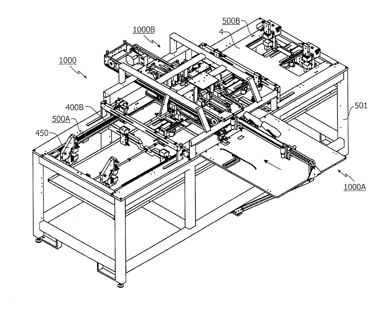
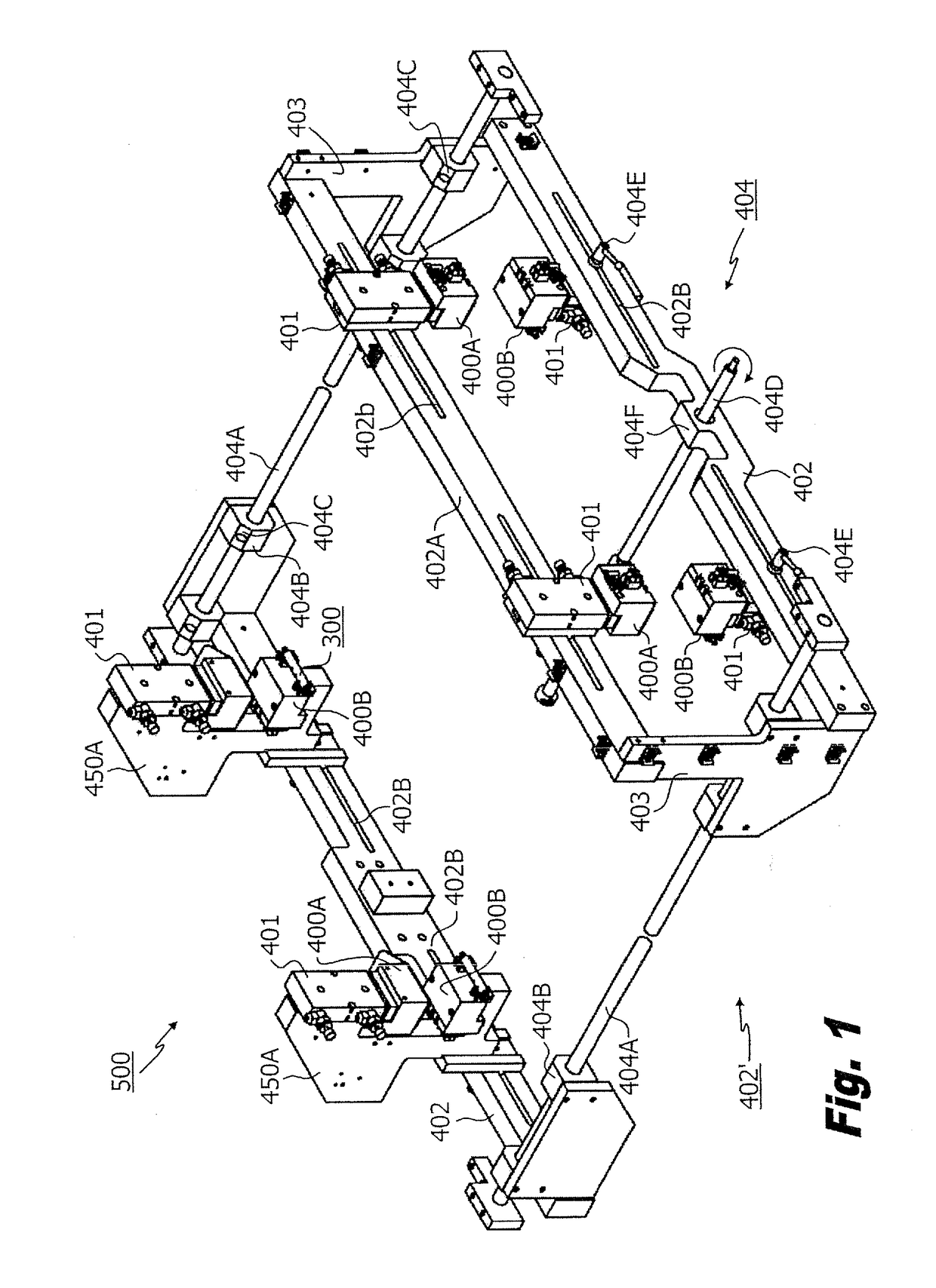
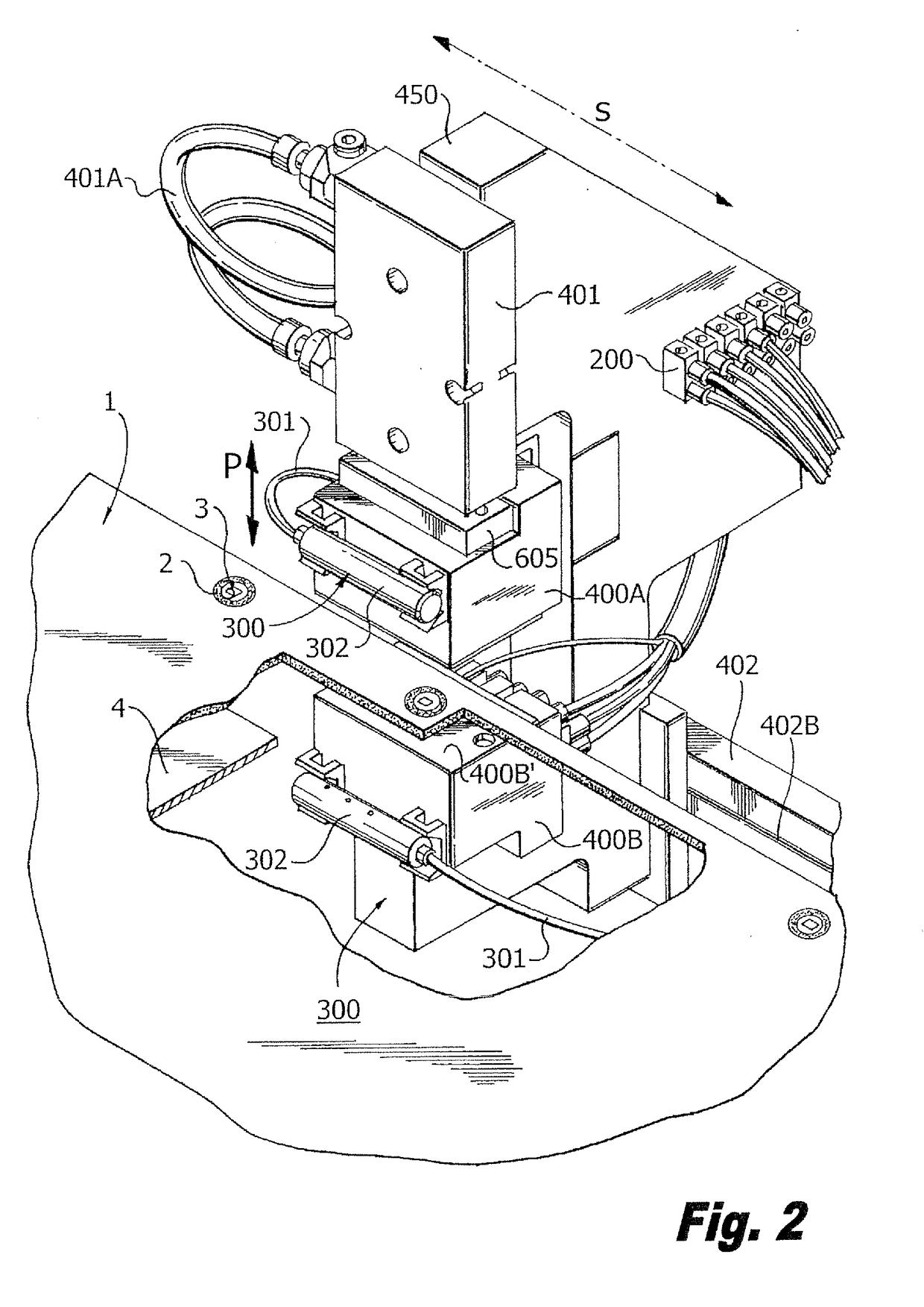
[0016]The present invention relates to an inductive thermal bonding system includes at least one inductive bonding or heating member containing a magnetic E-shaped inductive core and a coil bounding a central member of the E-shaped inductive core. A rigid cover plate allows high and predictable temperature rate-of-change during use and reduced thermal cycling time without risk of detriment. Adaptive solid copper pads on multiplayer bonding regions minimize bonding errors and improve reliability. A cooling system is provided for adaptively cooling both the bond head and the bonded stack. Single and paired inductive heating members may be employed, and may also be alternatively controlled and positioned to aid generation of multiplayer bonding subassemblies distant from an edge of a multiplayer sheet construct.
[0040]According to another optional embodiment of the present invention there is provided an adjustable inductive bonding system, wherein: the means for securely positioning, further comprises: at least a second support bar member, one of the inductive bonding head members on the first support bar member and the other of the inductive bonding head members on the second support bar member, the means for sliding enabling independent positioning of each the first and second inductive bonding head members independent from the other for enhanced ease of use.

Problems solved by technology

Unfortunately, the Gallego '157 system provides substantial manufacturing disadvantages and limitations which have not been overcome in the related art and for which technical appreciation is lacking.
These limitations and disadvantages include, but are not limited to:(a) A requirement for a U- or C-shaped inductive bonding core mechanism which in-turn fixes induction within the extending bonding arms of both sides in coaxial positions with one another, thereby allowing only axial repositioning depending upon a multiplayer thickness and preventing respective lateral displacement between arms for use as single-side bonding heads and prevents use in mid-layer and mid-sheet sub-assembly positioning (the C- or U-shape cannot be broken without inductive failure) resulting in a loss of manufacturing efficiency.(b) A requirement for a defined reserve region on each sheet to include a flat copper winding with at least one turn in short-circuit so that upon use the induced current in the short-circuit raises temperature.
Unfortunately, this requires (a) costly and time consuming intricate circuitry winding construction within each short circuit, (b) a risk of mis-alignment of such short circuits and such particular windings, (c) and slowed heat-up induction time due to the non-copper coated portions between each ring of the winding and of each short-circuit preventing direct conductive thermal transfer.(c) A requirement for a control system that operates both inductive sides of the U- or C-shaped inductive bonding mechanism in tandem from a single core; thereby preventing a control system adaptive to vary an induction on a respective induction coil to tailor a heat-up cycle for layer thickness, to compensate for mis-positioning, to prevent the use of such a system to generate custom induction routines, and requiring extensively long induction / heating cycles.

Method used


Image

  • Bond head assembly and system
  • Bond head assembly and system
  • Bond head assembly and system

Examples


Embodiment Construction

[0053]Reference will now be made in detail to several embodiments of the invention that are illustrated in the accompanying drawings. Wherever possible, same or similar reference numerals are used in the drawings and the description to refer to the same or like parts or steps. The drawings are in simplified form and are not to precise scale. For purposes of convenience and clarity only, directional terms, such as top, bottom, up, down, over, above, and below may be used with respect to the drawings. These and similar directional terms should not be construed to limit the scope of the invention in any manner. The words “connect,”“couple,” and similar terms with their inflectional morphemes do not necessarily denote direct and immediate connections, but also include connections through mediate elements or devices.

[0054]As employed herein the phrases bonding head, bonding member, induction head, induction core, and core may be adaptively employed depending upon the descriptive environm...


PUM

PropertyMeasurementUnit
temperaturesaaaaaaaaaa

Abstract

An inductive thermal bonding system includes at least one inductive bonding or heating member containing a magnetic E-shaped inductive core and a coil bounding a central member of the E-shaped inductive core. A rigid cover plate allows high and predictable temperature rate-of-change during use and reduced thermal cycling time without risk of detriment. Adaptive solid copper pads on multiplayer bonding regions minimize bonding errors and improve reliability. A cooling system is provided for adaptively cooling both the bond head and the bonded stack. Single and paired inductive heating members may be employed, and may also be alternatively controlled and positioned to aid generation of multiplayer bonding subassemblies distant from an edge of a multiplayer sheet construct.

Description

CROSS REFERENCE TO RELATED APPLICATIONS[0001]This application claims priority from and is a continuation of U.S. Ser. No. 12 / 377,268 filed Mar. 24, 2010, the entire contents of which are incorporated by reference; which in turn claims §371 priority from PCT / US2007 / 77178 filed Aug. 30, 2007 which in turn claims priority from U.S. Provisional Patent Application Ser. No. 60 / 824,263 filed Aug. 31, 2006, the entire contents of which are herein incorporated by reference.BACKGROUND OF THE INVENTION[0002]1. Field of the Invention[0003]The present invention relates to an inductive bond head assembly, construction, and system for operating the same within a multiplayer bonding process. More specifically, the present invention relates to a bond head assembly containing separately operable bonding heads usable without connective circuitry.[0004]2. Description of the Related Art[0005]The related art involves U.S. Pat. No. 7,009,157 to Gallego, the entire contents of which are herein incorporated...

Claims


Application Information

Patent Timeline
Patent Type & Authority Applications(United States)
IPC IPC(8): B23K13/01H05B6/06H05K1/11H05B6/40H05K3/46H05K1/09
CPCB23K13/01H05K3/4611H05K1/09B23K2201/42H05B6/40H05B6/06H05K2203/11H05K1/11B23K2101/42H05B6/14H05K3/4638B23K1/002B23K3/0475B23K9/0956B23K37/003B23K37/0282H05K3/46
Inventor FARACI, ANTHONYSORTINO, GARY N.
Owner DUETTO INTEGRATED SYST
Learn More