
Radiation imaging apparatus, method of controlling the same, and radiation imaging system

a technology of radiation imaging apparatus and control method, applied in the field of radiation imaging apparatus, can solve the problems of complex system, increased cost, and inability to maintain the offset itself, and achieve the effect of simple and low-cost configuration

Inactive Publication Date: 2011-08-09
CANON KK
View PDF42 Cites 23 Cited by
  • Summary
  • Abstract
  • Description
  • Claims
  • Application Information

AI Technical Summary

Benefits of technology

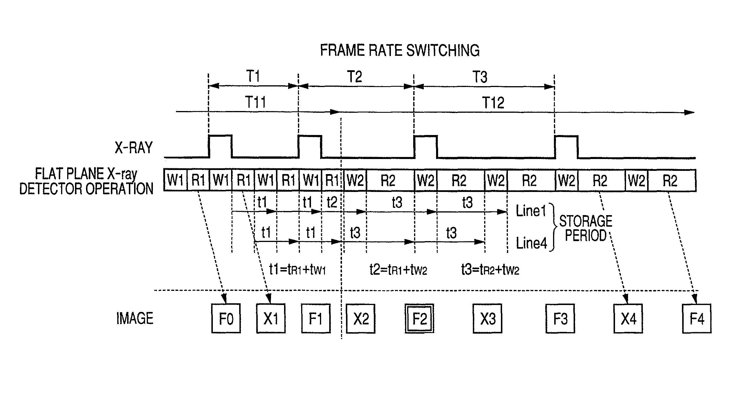
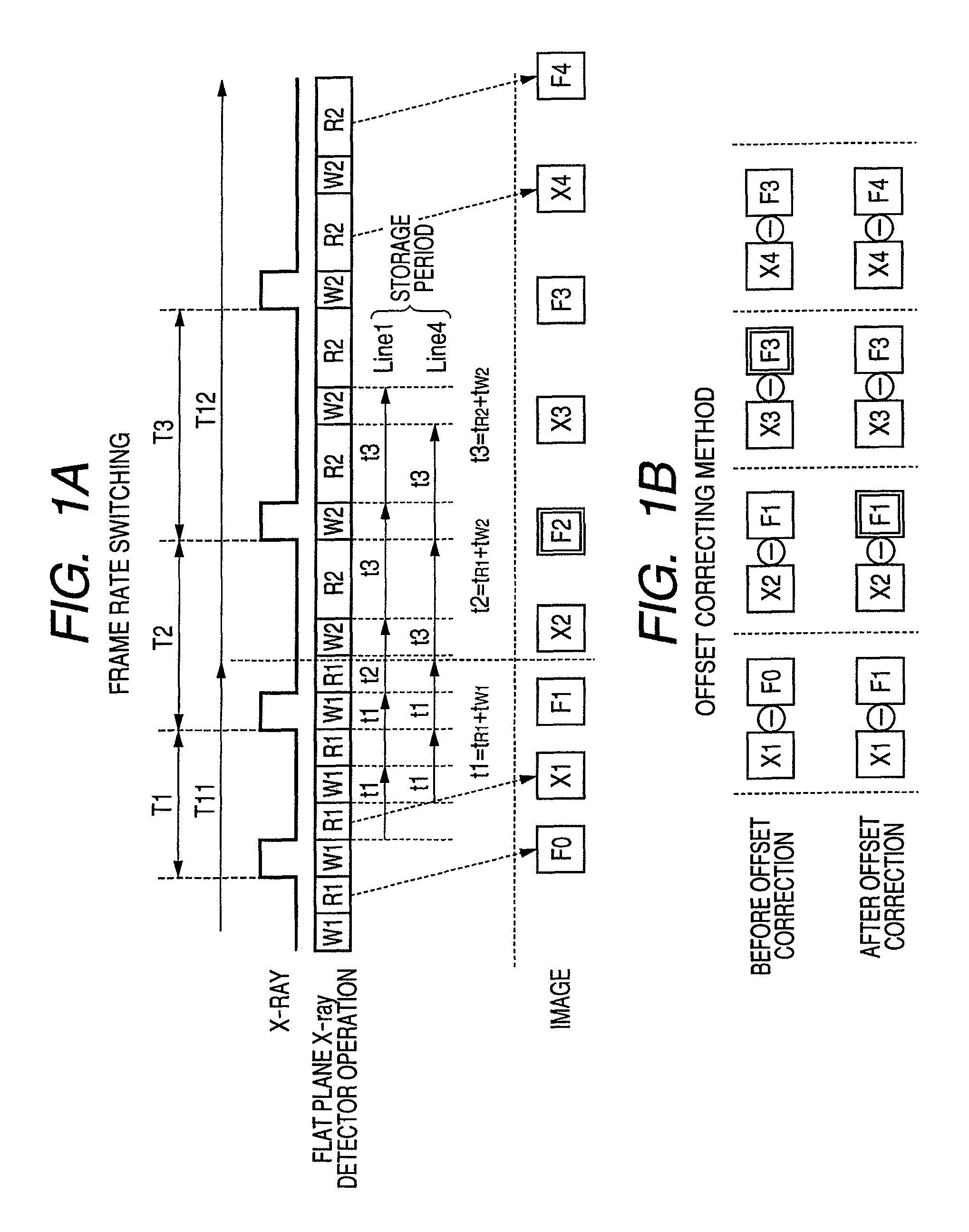
An object of the present invention is to provide a radiation imaging apparatus, a method of controlling the same, and a radiation imaging system which can deal with an arbitrary data acquisition period (frame rate) change instruction without increasing load and cost.
In accordance with the present invention, since it is unnecessary to store offset correction data every switching pattern of frame rate, offset correction can be made by a simple and low-cost configuration.

Problems solved by technology

However, with this method, in order to accommodate a large number of frame rates, it is necessary to have a great quantity of offset correction data.
Further, offset itself is not always constant.
From this it will be understood that the system is complicated and becomes expensive.

Method used


Image

  • Radiation imaging apparatus, method of controlling the same, and radiation imaging system
  • Radiation imaging apparatus, method of controlling the same, and radiation imaging system
  • Radiation imaging apparatus, method of controlling the same, and radiation imaging system

Examples


first exemplary embodiment

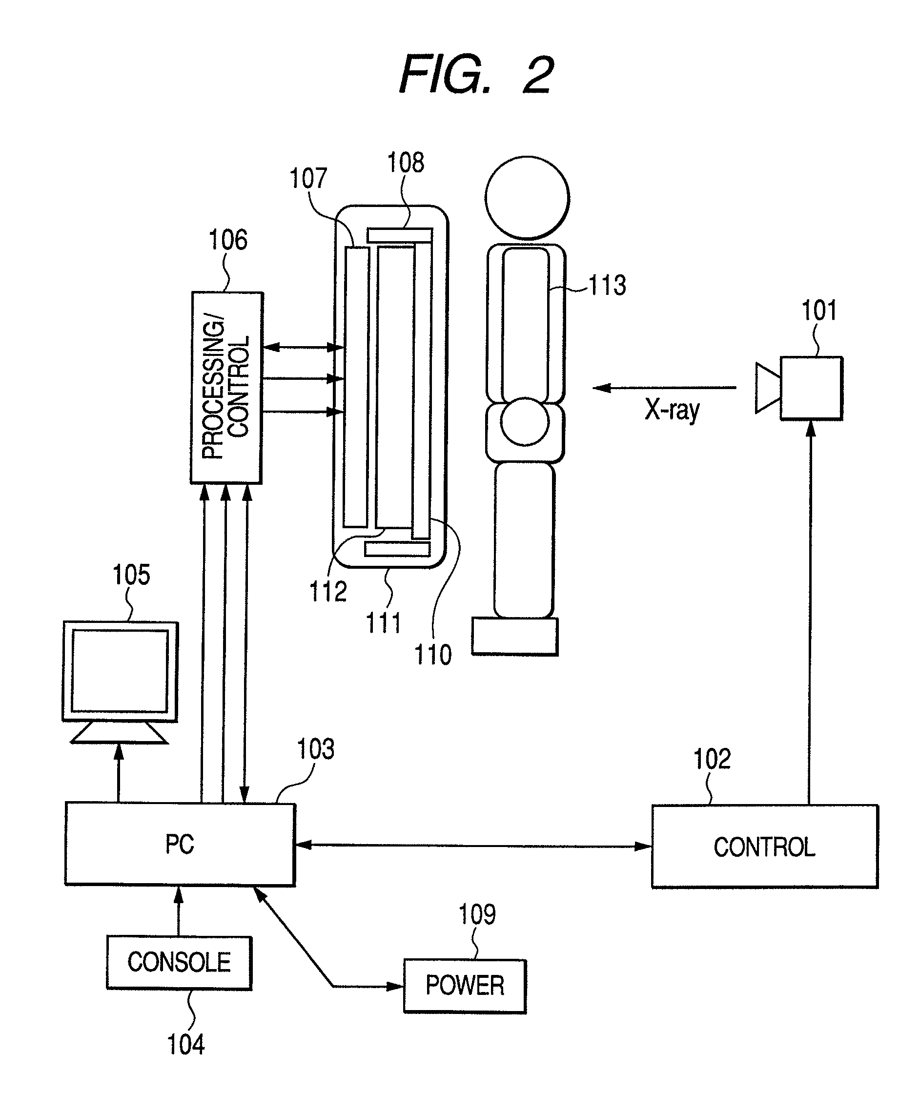
FIG. 2 is a diagram illustrating an example of the configuration of a digital radiation (X-ray) imaging system according to a first exemplary embodiment of the present invention. This digital radiation imaging system includes an X-ray source 101, an X-ray controller 102, and a digital radiation imaging apparatus. The X-ray source 101 is a radiation generator for generating and irradiating radioactive rays (hereinafter simply referred to as radiation as occasion may demand) (X-rays). The digital radiation imaging apparatus includes a control PC (Personal Computer) 103, a control console 104, a monitor 105, an image processing and control circuit 106, a power supply unit 109, and a flat plane X-ray detector 111. Specifically, the flat plane X-ray detector 111 is a two-dimensional area sensor including a system circuit 107, a read-out circuit 108, a sensor array 110 and a vertical drive circuit 112; and serves to convert radiation into an electric signal to output two-dimensional data....

second exemplary embodiment

FIGS. 8A and 8B are diagrams illustrating an example of the configuration of offset correction unit 602 according to the second exemplary embodiment of the present invention and a processing method therefor. The point of the present embodiment different from the first exemplary embodiment will now be described. The offset correction unit 602 of FIG. 8A differs from the offset correction unit 602 of FIG. 5A in that the offset correction unit 602 is configured by using image memory Mem corresponding to one image and buffer Buf which can hold data corresponding to one line of the flat plane X-ray detector 111. When the input memory switching signal is at High level, switch SW1 connects an output of the flat plane X-ray detector 111 to memory Mem. When the input memory switching signal is at Low level, the switch SW1 connects an output of the flat plane X-ray detector 111 to buffer Buf.

Moreover, the offset correction unit 602 of FIG. 8A differs from the offset correction unit 602 of FIG...

third exemplary embodiment

FIG. 9 is a circuit diagram illustrating an example of the configuration of flat plane X-ray detector 111 according to the third exemplary embodiment of the present invention, and illustrates a circuit diagram of flat plane X-ray detector 111 using MIS type conversion element 1001 as the conversion element. The point of the present embodiment different from the first exemplary embodiment will now be described. The flat plate X-ray detector 111 includes MIS type conversion elements 1001, transfer TFTs 1002, refreshing TFTs 1003, a refreshing power source 1004, a transfer vertical drive circuit 1005, a refreshing vertical drive circuit 1006, a sensor bias power source 1007, a refreshing line 1008, and sensor bias lines 1009.

In the MIS type conversion element 1001, as previously described with reference to FIG. 4B, there is the problem that when charges are accumulated at interface between A-Si layer 308 serving as photoelectric conversion layer and insulating layer 307 so that accumul...


PUM


Abstract

There are provided an apparatus capable of complying with arbitrary data acquisition period (frame rate) change instruction without increasing load and cost, and a method and a system for controlling such an apparatus. To realize this, in the present invention, there are included an area sensor for reading out an electric signal accumulated in a plurality of pixels arranged in a matrix, line by line, and a control unit for controlling the area sensor. The area sensor operates in a first operation for deriving radiation image data by reading during irradiation with radiation, and a second operation for deriving the radiation image data by reading during non-irradiation with radiation, alternately. The control unit switches a period for deriving the radiation image data during a time period from an end of the reading in the first operation until an end of the reading in the second operation.

Description

BACKGROUND OF THE INVENTION1. Field of the InventionThe present invention relates to a radiation imaging apparatus, a method of controlling such a radiation imaging apparatus, and a radiation imaging system.2. Description of the Related ArtIn recent years, with development of the semiconductor technology, there are put into practice and are popularized digital X-ray imaging apparatuses using a two-dimensionally arranged sensor in which conversion elements for converting light into an electric signal are formed on a glass substrate.In U.S. Pat. No. 6,453,008, there is described a radiation detector including plural offset memories having offset data which have been acquired in advance in correspondence with plural modes (sequential read-out, pixel addition, trimming, high frame rate and high irradiation), and which selectively uses an appropriate one of the offset memories in accordance with the corresponding mode.Moreover, in Japanese Patent Application Laid-Open No. 2004-194702, th...

Claims


Application Information

Patent Timeline
Patent Type & Authority Patents(United States)
IPC IPC(8): G01T1/20G01T1/00A61B6/00G01T1/24H04N5/32H04N5/341H04N5/357H04N5/374
CPCA61B6/032A61B6/4233A61B6/585H04N5/217H04N5/325G01T1/247A61B6/541H01L27/14643H04N23/81
Inventor YAGI, TOMOYUKIINOUE, HITOSHISHIOZAWA, HIDETO
Owner CANON KK
Learn More