Betatron with a removable accelerator block

a technology of accelerator block and betatron, which is applied in the direction of x-ray apparatus, measurement devices, instruments, etc., can solve the problem of large mass movement and achieve the effect of simplifying the maintenance and repair of the accelerator block

Active Publication Date: 2011-08-09
SMITHS HEIMANN
View PDF25 Cites 2 Cited by
  • Summary
  • Abstract
  • Description
  • Claims
  • Application Information

AI Technical Summary

Benefits of technology

It is therefore an object of the present invention to provide a betatron that enables simplified maintenance and repair of the accelerator.
The opposing front sides of the inner yoke parts are designed and arranged with mirror symmetry to one another. The symmetry plane in this regard is advantageously oriented so that the rotational symmetry axis of the inner yoke is perpendicular to it. This results in an advantageous field distribution in the air gap between the front sides by which the electrons in the betatron tube are kept in an orbit.
Furthermore, at least one main field coil can be arranged on the inner yoke, particularly on a neck or a shoulder of the inner yoke. This has the result that substantially the entire magnetic flux produced by the main field coil is guided through the inner yoke. In an advantageous manner, the betatron has two main field coils, a main field coil being arranged on each of the inner yoke parts. This leads to an advantageous distribution of the magnetic flux on the inner yoke parts.
In an embodiment of the invention, the betatron has a guide rail and / or a stop for the accelerator block. The guide rail enables a precise positioning of the accelerator block within the outer yoke. The stop establishes the end position of the accelerator block. In other respects, the guide rail simplifies the removal or insertion of the accelerator block, for example, in that the accelerator block rolls or glides over the guide rail.
In an embodiment, a betatron of the invention has a component for fixing the parts of the outer yoke in the closed position. These components can be, for example, screws or nuts, etc. and prevent the outer yoke from opening particularly during betatron operation. Preferably, the means for fixing the parts of the outer yoke are accessible through the lead shielding. It is possible thereby to loosen or restore the fixation without removing the lead shielding.
Optionally, the betatron has at least one round plate between the inner yoke parts, whereby the round plate is arranged so that its longitudinal axis coincides with the rotational symmetry axis of the inner yoke. Because of the permeability of the round plate material, the magnetic field in the region of the round plates is stronger than in the air gap, without round plates, between the front sides of the inner yoke parts. This makes it possible to influence the Wideroe condition by means of the design of the round plate(s) and thereby the orbit radius of the accelerated electrons within the betatron tube.

Problems solved by technology

This has the disadvantage that in each case large masses must be moved and devices suitable for this are needed.

Method used


Image

  • Betatron with a removable accelerator block
  • Betatron with a removable accelerator block
  • Betatron with a removable accelerator block

Examples


Embodiment Construction

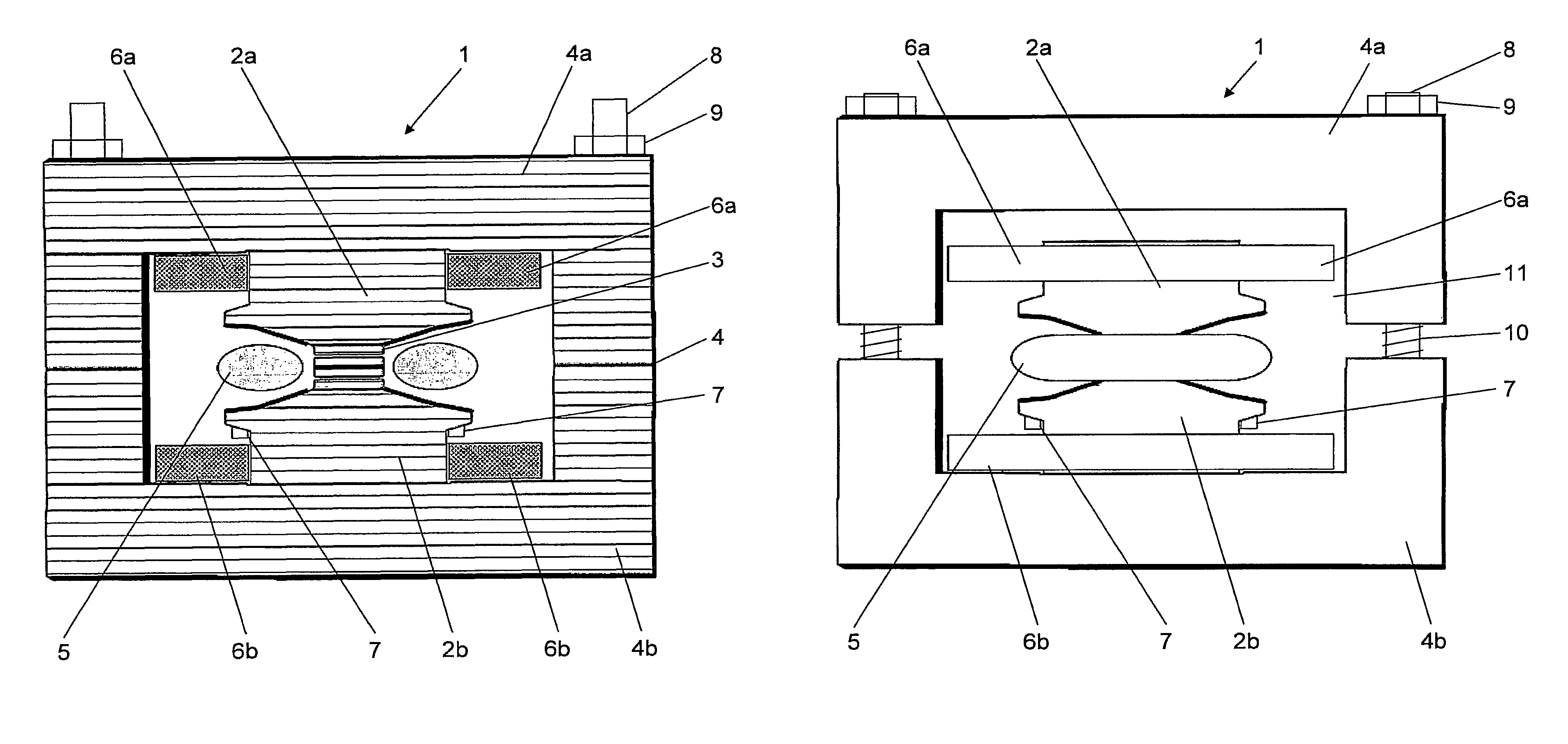
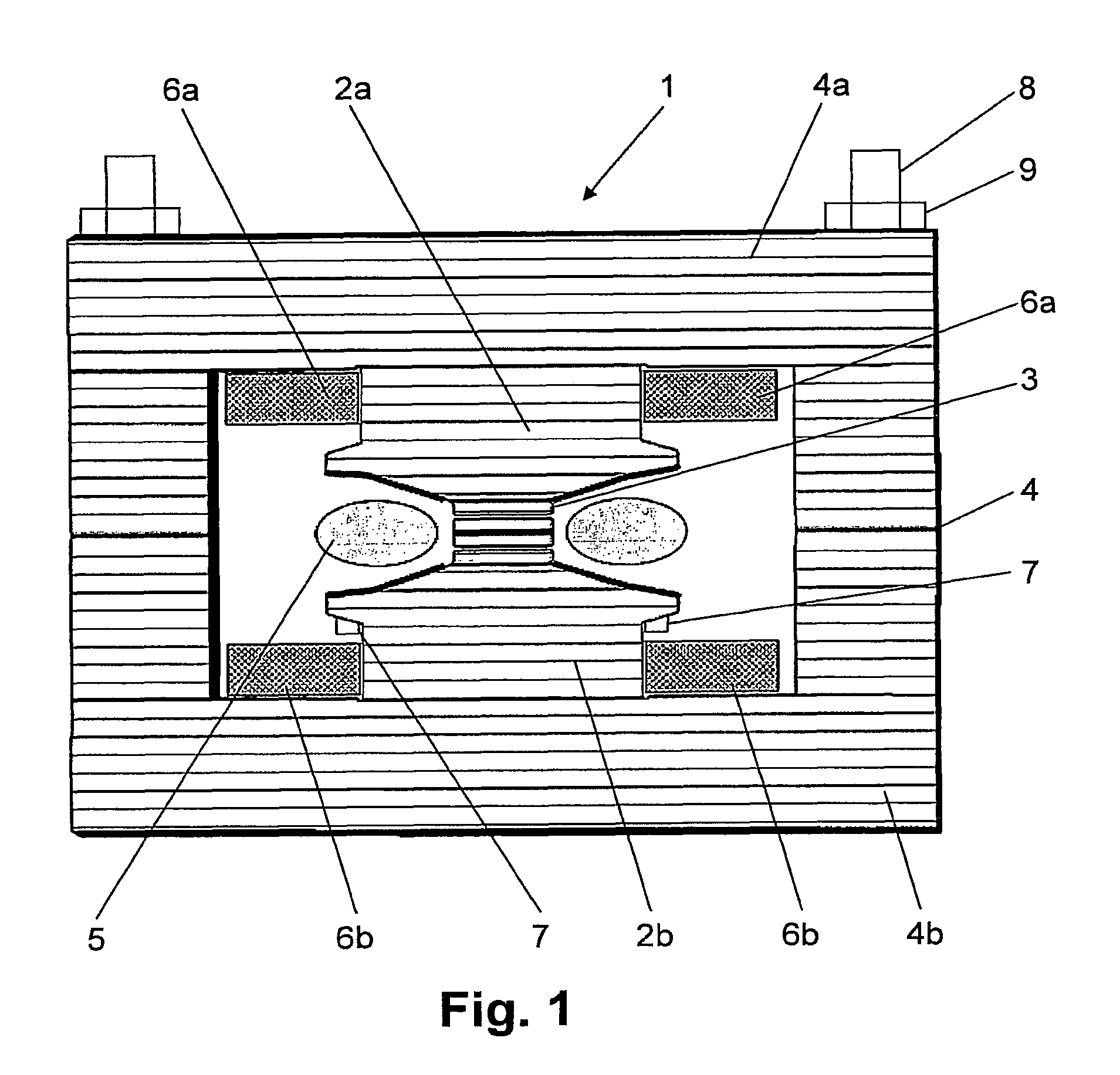
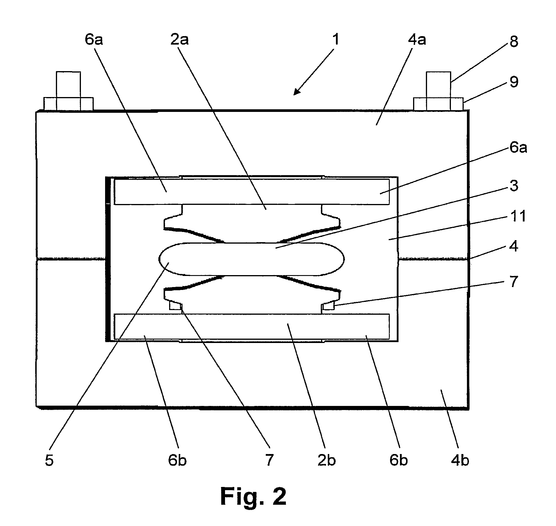
FIG. 1 shows the schematic structure of a preferred betatron 1 in cross section. The accelerator block includes a rotationally symmetric inner yoke of two spaced-apart parts 2a, 2b, a torus-shaped betatron tube 5 arranged between inner yoke parts 2a, 2b, and two main field coils 6a and 6b.

Main field coils 6a and 6b are arranged on shoulders of inner yoke parts 2a or 2b. The magnetic field produced by them penetrates inner yoke parts 2a and 2b, whereby the magnetic circuit is closed by a two-part outer yoke 4, which connects the inner yoke parts 2a and 2b. The shape of the inner and / or outer yoke can be selected by the person skilled in the art depending on the application and can deviate from the shape shown in FIG. 1. Only one or more than two main field coils may also be present.

Betatron 1 furthermore has optional round plates 3 between inner yoke parts 2a, 2b, whereby the longitudinal axis of round plates 3 corresponds to the rotational symmetry axis of the inner yoke. The magne...


PUM


Abstract

A betatron is provided, particularly in an x-ray inspection station, comprising an accelerator block that is provided with a rotationally symmetrical inner yoke composed of two spaced-apart pieces, at least one main field coil, and a toroidal betatron tube which is disposed between the pieces of the inner yoke. The betatron further comprises an outer yoke which embraces the accelerator block, connects the two pieces of the inner yoke, and has at least one lateral opening, as well as a lead shield that accommodates the accelerator block and the outer yoke. The outer yoke is composed of at least two parts which are movable relative to one another between an open and a closed position. The accelerator block can be laterally removed from the opening of the outer yoke that is in the open position.

Description

BACKGROUND OF THE INVENTION1. Field of the InventionThe present invention relates to a betatron with a removable accelerator block, particularly for producing x-radiation in an x-ray inspection system.2. Description of the Background ArtX-ray inspection systems are used, as is well-known, in the inspection of large-volume articles such as containers and motor vehicles for illegal contents such as weapons, explosives, or contraband goods. In so doing, x-radiation is produced and directed at the article. The x-radiation attenuated by the article is measured by a detector and analyzed by an evaluation unit. Therefore, a conclusion can be reached on the nature of the article. This type of x-ray inspection system is known, for example, from European Pat. No. EP 0 412 190 B1, which corresponds to U.S. Pat. No. 5,065,418.Betatrons are used to generate x-radiation with the energy of more than 1 MeV needed for the inspection. These are circular accelerators in which electrons are held in an ...

Claims


Application Information

Patent Timeline
Patent Type & Authority Patents(United States)
IPC IPC(8): H05H11/00
CPCH05H11/04H05G2/00
Inventor BERMUTH, JOERGGEUS, GEORGHESS, GREGORVIEHBOECK, URS
Owner SMITHS HEIMANN
Why Eureka
Try Eureka