Apparatus for the heat treatment of a web of textile material

A technology for textiles and fabric webs, applied in lighting and heating equipment, heating devices, progressive dryers, etc., can solve the problems of not completely avoiding heat loss, increase costs, etc., and achieve the effect of simple maintenance and cleaning operations

Inactive Publication Date: 2015-07-08
A MONFORTS TEXTILMASCHINEN GMBH & CO KG
View PDF12 Cites 0 Cited by
  • Summary
  • Abstract
  • Description
  • Claims
  • Application Information

AI Technical Summary

Problems solved by technology

This is associated with corresponding costs; additional heat losses cannot be completely avoided
In addition, the overall height required for the installation is significantly increased, which likewise means an increase in costs for the building in which the installation is to be accommodated.

Method used


Image

  • Apparatus for the heat treatment of a web of textile material
  • Apparatus for the heat treatment of a web of textile material
  • Apparatus for the heat treatment of a web of textile material

Examples


Embodiment Construction

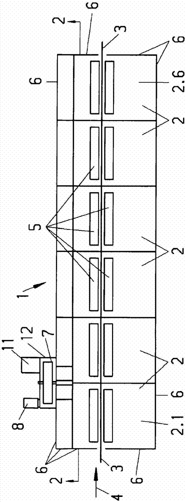
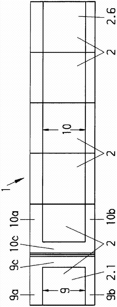
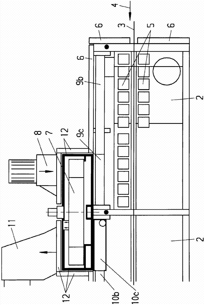
[0021] as from Figures 1 to 3 As can be seen, in the first exemplary embodiment, the device for the heat treatment is designed here as a tenter frame 1 . The tenter frame consists of a large number, here six, of substantially identically constructed chambers 2 . The textile web 3 can be transported horizontally in the direction of the arrow 4 through the tenter frame 1 and guided there by means of transport chains and grippers. Each chamber 2 comprises means for blowing the treatment gas onto the fabric web 3, consisting at least of nozzle boxes 5 arranged above and below the fabric web 3, a circulating air blower, means for heating the treatment gas and means for guiding and means for regulating the process gas (circulation air) guided in the circulation.

[0022] The tenter frame 1 is largely surrounded by a housing 6 ; on the input side of the tenter frame 1 there is an input slot for the textile web 3 and on the output side an output slot is provided.

[0023] Furtherm...


PUM


Abstract

The invention relates to an apparatus for the heat treatment of a web of textile material (3) comprising a housing (6), means for guiding the web of material (3) in the housing (6), means for blowing heated treatment gas (5) onto the web of material (3), at least part of the treatment gas being supplied as fresh air and exhaust gas being carried away, and a heat wheel (7) for preheating the fresh air by means of the exhaust gas. It is intended to improve the apparatus in such a way as to create lines for indirectly preheating fresh air by means of exhaust air without any significant additional expenditure and without the height of the apparatus being any greater, or significantly greater, than in the case of apparatuses without preheating. This is achieved by the heat wheel (7) being connected directly to warm sides of the ducts (9, 10) for the fresh air and for the exhaust air, the warm sides of the ducts (9, 10) being routed exclusively inside the housing (6).

Description

technical field [0001] The invention relates to an apparatus for thermally treating a textile web comprising a housing; means for guiding the textile web in the housing; means for blowing heated treatment gas onto the textile web, wherein A first channel is provided for supplying fresh air, which is at least partly the process gas, and wherein a second channel is provided for leading off exhaust air; and at least one heating wheel for preheating the fresh air by means of exhaust air . Background technique [0002] Such devices are known per se. They are designed, for example, as tenter frames or blowers. [0003] Stenter frames are generally divided into a large number of chambers, also called fields. The fabric web runs longitudinally through the chambers in an essentially horizontal plane, wherein the fabric web is stretched between two chains at its longitudinal edges. Process gas, for example circulating air, is blown onto the fabric web. Such tenter frames are know...

Claims


Application Information

Patent Timeline
Patent Type & Authority Patents(China)
IPC IPC(8): F26B13/10F26B23/00
CPCF26B13/10F26B23/002Y02P70/10F26B23/00
Inventor G·鲍姆
Owner A MONFORTS TEXTILMASCHINEN GMBH & CO KG
Why Eureka
Try Eureka