Waste heat collecting device used for discharging end of ultra high temperature vertical kiln

A waste heat collection and discharge end technology, applied in the field of high-temperature shaft kiln supporting devices, can solve the problems of low heat collection efficiency, easy oxidation and erosion, short service life, etc., and achieves good energy saving effect, quick and easy assembly, and long service life Effect

Inactive Publication Date: 2017-08-15
山东泰贝利尔环保科技有限公司
View PDF0 Cites 0 Cited by
  • Summary
  • Abstract
  • Description
  • Claims
  • Application Information

AI Technical Summary

Problems solved by technology

[0004] The present invention aims at the technical defects of the prior art, and provides a waste heat collection device for the discharge end of the ultra-high temperature shaft kiln, so as to solve the problem of heat collection efficiency of the waste heat collection device used for the discharge end of the high temperature shaft kiln in the prior art. lower technical issues
[0005] Another technical problem to be solved by the present invention is that the waste heat collection device used in the discharge end of the high-temperature shaft kiln in the prior art is easily oxidized and corroded inside under high-temperature conditions, and has a short service life.
[0006] Another technical problem to be solved by the present invention is that in the prior art, the waste heat collection device used at the discharge end of the high-temperature shaft kiln is easily blocked inside.

Method used


Image

  • Waste heat collecting device used for discharging end of ultra high temperature vertical kiln

Examples


Embodiment 1

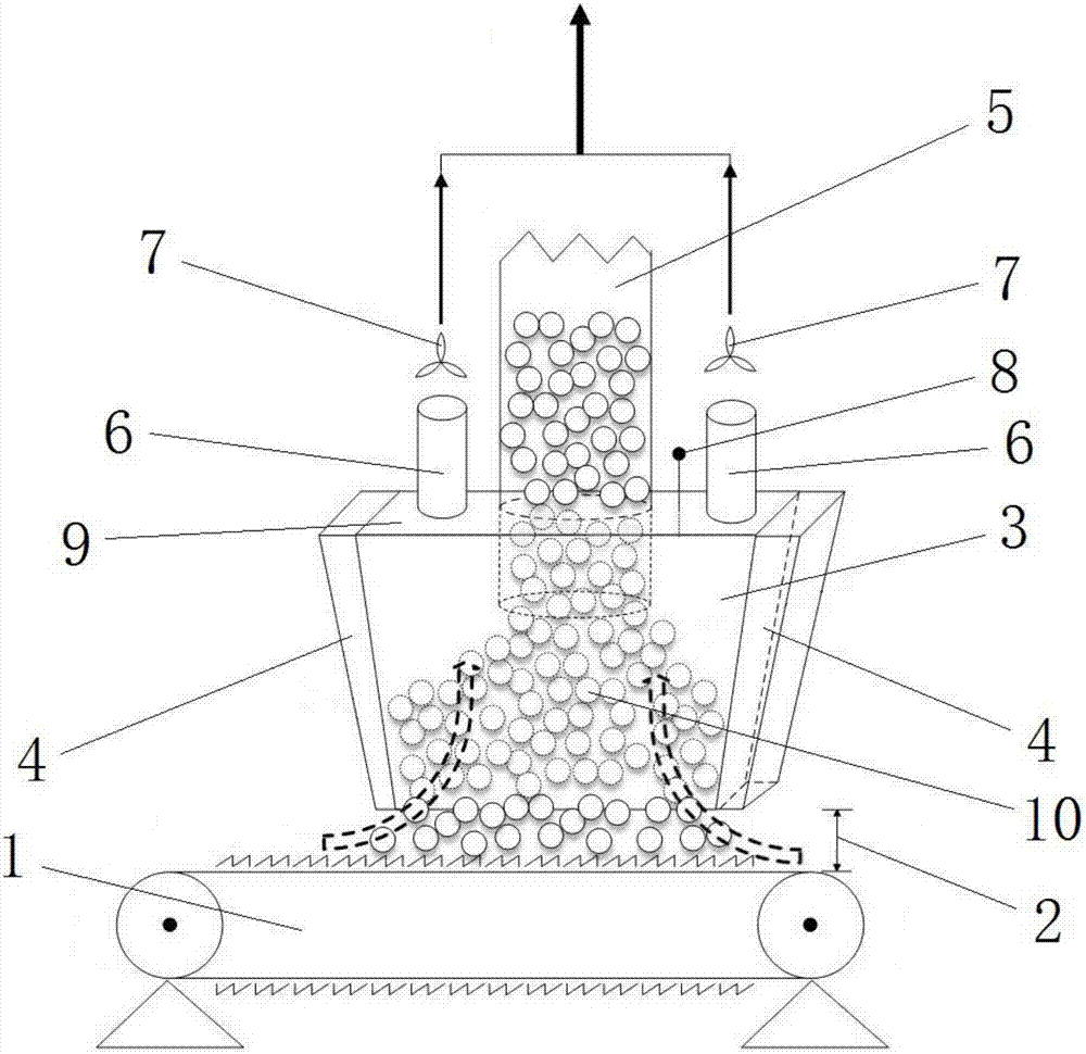
[0032] A waste heat collection device for the discharge end of an ultra-high temperature shaft kiln, including a conveyor 1, a gap 2, a shell 3, a heat insulation layer 4, a shaft kiln discharge pipe 5, a waste heat air duct 6, a fan 7, and a temperature sensor 8 , end cover 9, wherein the shell 3 is located above the conveyor 1, there is a gap 2 between the shell 3 and the conveyor 1, the lower port of the shell 3 is open, and the upper port is connected to the end cover 9, the shaft kiln discharge pipe 5 and the waste heat air duct 6 are respectively connected to the end cover 9, the lower port of the shaft kiln discharge pipe 5 and the lower port of the waste heat air duct 6 all extend into the inside of the housing 3, and the outer periphery of the housing 3 The heat insulation layer 4 is fixedly connected, the fan 7 is fixedly connected to the upper port of the waste heat air duct 6, the temperature sensor 8 is fixedly connected to the end cover 9, and the temperature prob...

Embodiment 2

[0043] A waste heat collection device for the discharge end of an ultra-high temperature shaft kiln, including a conveyor 1, a gap 2, a shell 3, a heat insulation layer 4, a shaft kiln discharge pipe 5, a waste heat air duct 6, a fan 7, and a temperature sensor 8 , end cover 9, wherein the shell 3 is located above the conveyor 1, there is a gap 2 between the shell 3 and the conveyor 1, the lower port of the shell 3 is open, and the upper port is connected to the end cover 9, the shaft kiln discharge pipe 5 and the waste heat air duct 6 are respectively connected to the end cover 9, the lower port of the shaft kiln discharge pipe 5 and the lower port of the waste heat air duct 6 all extend into the inside of the housing 3, and the outer periphery of the housing 3 The heat insulation layer 4 is fixedly connected, the fan 7 is fixedly connected to the upper port of the waste heat air duct 6, the temperature sensor 8 is fixedly connected to the end cover 9, and the temperature prob...


PUM


Abstract

The invention provides a waste heat collection device for the discharge end of an ultra-high-temperature shaft kiln. The device is equipped with a shell for waste heat collection at the discharge port of the lower end of the conventional shaft kiln, so that the shaft kiln fired The material flows through the shell first and then falls on the conveyor, and the shell acts as a waste heat collection chamber to collect waste heat. On this basis, a waste heat air duct is set on the end cover of the shell, and the fan is used to guide the wind upward, so that the external air flows into the shell through the gap between the shell and the conveyor, and then is transported upwards to the outside through the waste heat air duct, effectively Helps alleviate the problem of material dust blockage. In addition, the heat insulation layer wrapped around the shell can play a role in heat preservation and improve the recovery rate of waste heat; the temperature sensor on the end cover can monitor the internal temperature of the shell, and can cooperate with the control system to control the temperature according to the temperature. Fan speed. The invention achieves good technical effect through innovative technical improvement, and has wide promotion prospect.

Description

technical field [0001] The invention relates to the technical field of supporting devices for a high-temperature shaft kiln, in particular to a waste heat collection device used at the discharge end of an ultra-high-temperature shaft kiln. Background technique [0002] Shaft kiln refers to a vertical continuous kiln consisting of a steel shell with a vertical axis and a refractory brick lining, used for firing bulk bulk materials. It usually uses liquid or gaseous fuel, and its thermal efficiency is higher than that of tunnel kiln. It is currently widely used in the domestic refractory industry. [0003] The materials fired in the shaft kiln still have a lot of heat when they are discharged. If they are discharged directly, energy will be wasted on the one hand, and a longer cooling time will be required on the other hand, which is not conducive to the advancement of the process. Most enterprises using shaft kilns in the industry have not adopted waste heat collection techn...

Claims


Application Information

Patent Timeline
Patent Type & Authority Applications(China)
IPC IPC(8): F27B1/10F27B1/26F27D17/00
CPCF27B1/10F27B1/26F27D17/004
Inventor 张会友刘辉张立伟
Owner 山东泰贝利尔环保科技有限公司
Why Eureka
Try Eureka