Phase change heat collecting-heat dissipation wall system operating under full working conditions

A heat dissipation wall and full working condition technology, applied in the field of phase change heat collection-radiation wall system, can solve the problems of low heat storage and discharge rate, poor thermal insulation performance, and reduced utilization rate of stored heat in phase change heat collection and heat storage walls , to achieve the effect of reducing the incoming of solar radiant heat, good heat preservation and heat insulation, and reducing the loss of radiant heat

Active Publication Date: 2018-09-28
XI'AN UNIVERSITY OF ARCHITECTURE AND TECHNOLOGY
View PDF9 Cites 13 Cited by
  • Summary
  • Abstract
  • Description
  • Claims
  • Application Information

AI Technical Summary

Problems solved by technology

[0004] (1) The heat storage capacity of the traditional heat collection and storage wall is limited, which cannot meet the thermal comfort demand at night; the heat storage and release rate of the phase change heat collection and storage wall is low, and the heating efficiency is low
[0005] (2) Poor thermal insulation performance, resulting in more heat loss in winter and lower utilization rate of stored heat
[0006] (3) The heat insulation performance is poor, resulting in overheating in the room in summer, which does not meet the thermal comfort requirements in summer

Method used


Image

  • Phase change heat collecting-heat dissipation wall system operating under full working conditions
  • Phase change heat collecting-heat dissipation wall system operating under full working conditions
  • Phase change heat collecting-heat dissipation wall system operating under full working conditions

Examples


Embodiment Construction

[0035] The present invention will be described in detail below in conjunction with the accompanying drawings and specific embodiments, where the schematic embodiments and descriptions of the present invention are used to explain the present invention, but not to limit the present invention.

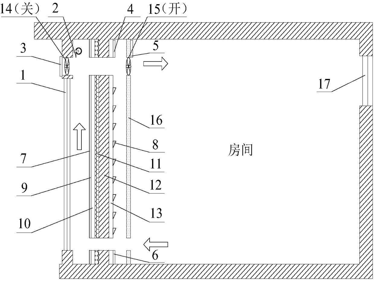
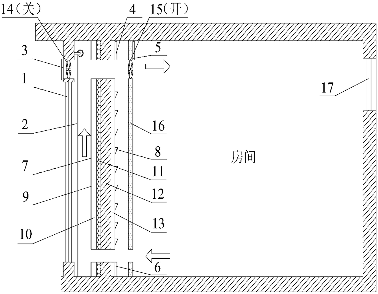
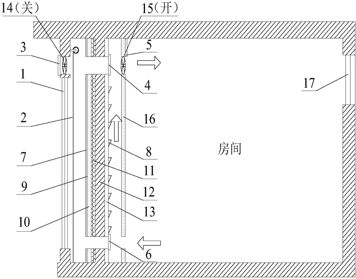
[0036] refer to Figure 1(a)-Figure 1(d) As shown, the present invention proposes a phase-change heat collection-radiation wall system operated under full working conditions, including a glass cover plate 1 arranged on the window of the room (in this embodiment, on the window opposite to the north-facing window 17) A thermal storage wall 12 is provided inside the glass cover 1, and a decorative panel 16 is provided inside the thermal storage wall 12; the top opening of the glass cover 1 communicates with the outside, and the top and bottom openings of the thermal storage wall 12 form Double-chamber, the top and bottom openings of the decorative plate 16 communicate with the room, and an o...


PUM


Abstract

The invention belongs to a phase change heat collecting-heat dissipation wall system operating under full working conditions in the technical field of building energy saving. The phase change heat collecting-heat dissipation wall system comprises a glass cover plate arranged on a room window, a heat storage wall is arranged inside the glass cover plate, and a decorative plate is arranged inside the heat storage wall. A top opening of the glass cover plate communicates with the outdoor, and a double-cavity channel is formed by opening of the top end and the bottom of the heat storage wall. Thetop end and a bottom opening of the decorative plate communicate with a room, and an outdoor exhaust suction fan and an indoor air supply suction fan are separately installed at the top opening of theglass cover and the top opening of the decorative plate. A thermal insulation roller blind is installed inside the glass cover. The heat storage wall realizes winter heating and summer cooling of a phase change material with different phase transition temperatures, an outside phase change material with a perforated aluminum plate attached to the outer side and an inside phase change material surface longitudinal vortex generator by starting different operating modes in winter and summer. The phase change heat collecting-heat dissipation wall system has broad application prospects and popularization value in areas at which solar energy resources are enriched and the temperature difference between day and night is large.

Description

technical field [0001] The invention belongs to the technical field of building energy conservation, and relates to a phase-change heat collection-radiation heat-dissipation material that adopts phase change materials with different phase change temperatures, and is combined with thermal insulation roller blinds and fans to adjust the indoor thermal environment and can be used under working conditions throughout the year. wall system. Background technique [0002] The northern part of my country is relatively cold and is the main area for heating. The heating energy consumption of northern cities and towns is 184 million tce, accounting for 21% of building energy consumption. volume continued to grow. Therefore, reducing building heating energy consumption is of great significance for building energy conservation. Improving the thermal insulation and heat storage performance of the building envelope and utilizing renewable resources such as solar energy can reduce building ...

Claims


Application Information

Patent Timeline
Patent Type & Authority Applications(China)
IPC IPC(8): E04B2/00E04B1/76F24F5/00
CPCF24F5/0075E04B1/7675E04B2/00Y02E10/40
Inventor 杨柳侯立强刘衍刘江王梦媛
Owner XI'AN UNIVERSITY OF ARCHITECTURE AND TECHNOLOGY
Why Eureka
Try Eureka