A Distributed Heat Storage System

A heat storage system, distributed technology, applied in the direction of cooling/ventilation/heating transformation, using liquid cooling for modification, etc., can solve the problems of adjacent space restrictions, achieve the goal of increasing heat storage rate, extending heat conduction path, and improving flexibility Effect

Active Publication Date: 2020-12-29
XIAN AVIATION COMPUTING TECH RES INST OF AVIATION IND CORP OF CHINA
View PDF13 Cites 0 Cited by
  • Summary
  • Abstract
  • Description
  • Claims
  • Application Information

AI Technical Summary

Problems solved by technology

[0005] In order to solve the problem of adjacent space limitations when high power consumption devices in electronic equipment use phase change materials to store heat, the present invention provides a distributed heat storage system that can overcome this problem and has a good heat storage rate

Method used


Image

  • A Distributed Heat Storage System

Examples


Embodiment Construction

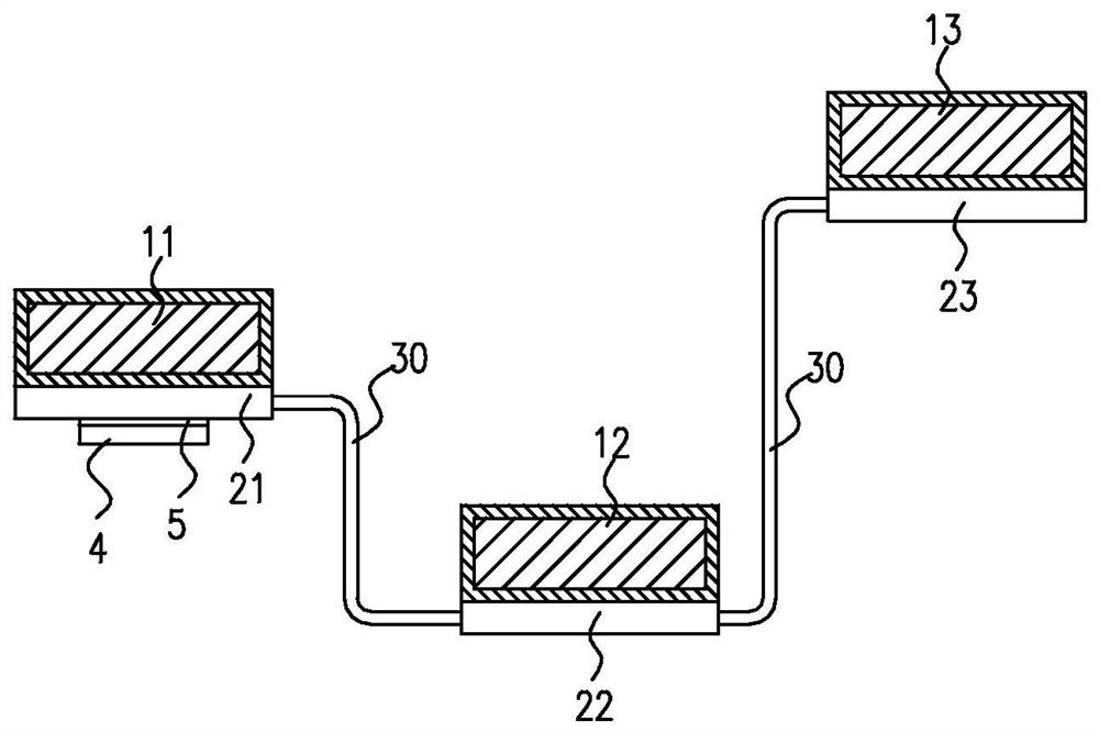
[0023] In the embodiment of the present invention, the phase change material (PCM) is used to absorb the heat generated during the operation of the internal components of the electronic equipment, and the stored heat is proportional to the volume of the phase change material that can be filled. As electronic equipment is becoming more and more compact, when PCM is required for heat storage in engineering, there is no space for heat storage devices around high-power devices in many electronic equipment, or the space provided is not enough to meet their heat storage needs. In order to solve this problem, the present invention provides a distributed heat storage system, which can make full use of the internal space of electronic equipment, has good heat storage rate, can be flexibly adjusted according to the specific structure of electronic equipment, and has wide adaptability.

[0024] Specifically, the present invention provides a distributed heat storage system, which can make ...


PUM


Abstract

The invention provides a distributed heat storage system. The system comprises at least two heat storage units (10) and at least two heat conducting plates 920); and the heat storage units make contact with the corresponding heat conducting plates, and the heat conducting plates are connected in series through heat pipes (30).

Description

technical field [0001] The invention belongs to the field of thermal management of electronic equipment, and relates to a distributed heat storage system. Background technique [0002] With the development of the electronic industry, the performance of electronic equipment is required to be continuously improved, the degree of integration is continuously improved, and the assembly density is becoming more and more compact. High power consumption electronic components are enclosed inside the electronic equipment, the traditional natural heat dissipation is increasingly unable to meet its heat dissipation requirements, and the active forced air cooling or liquid cooling makes the thermal management system complicated due to the introduction of moving parts and fluid pipelines. It violates the requirements of high-density assembly and reduces reliability. The thermal management of electronic components is carried out by using the characteristic that the temperature of the phas...

Claims


Application Information

Patent Timeline
Patent Type & Authority Patents(China)
IPC IPC(8): H05K7/20
CPCH05K7/2029
Inventor 吴波赵亮杨明明焦超锋
Owner XIAN AVIATION COMPUTING TECH RES INST OF AVIATION IND CORP OF CHINA
Why Eureka
Try Eureka