
Electromagnetic relay

a technology of electromagnetic relays and relays, applied in the field of electromagnetic relays, can solve the problems of complex and difficult assembly of electromagnetic relays, inability to electromagnetically isolate very well, and inability to achieve very good electromagnetic isolation, etc., and achieves the effects of reducing manufacturing costs, facilitating assembly, and facilitating assembly

Inactive Publication Date: 2011-08-09
EXCEL CELL ELECTRONICS
View PDF11 Cites 22 Cited by
  • Summary
  • Abstract
  • Description
  • Claims
  • Application Information

AI Technical Summary

Benefits of technology

[0007]Therefore, an object of the present invention is to provide an electromagnetic relay that is easy to assemble, that costs relatively less for manufacturing, and that has a relatively higher breakdown voltage value.

Problems solved by technology

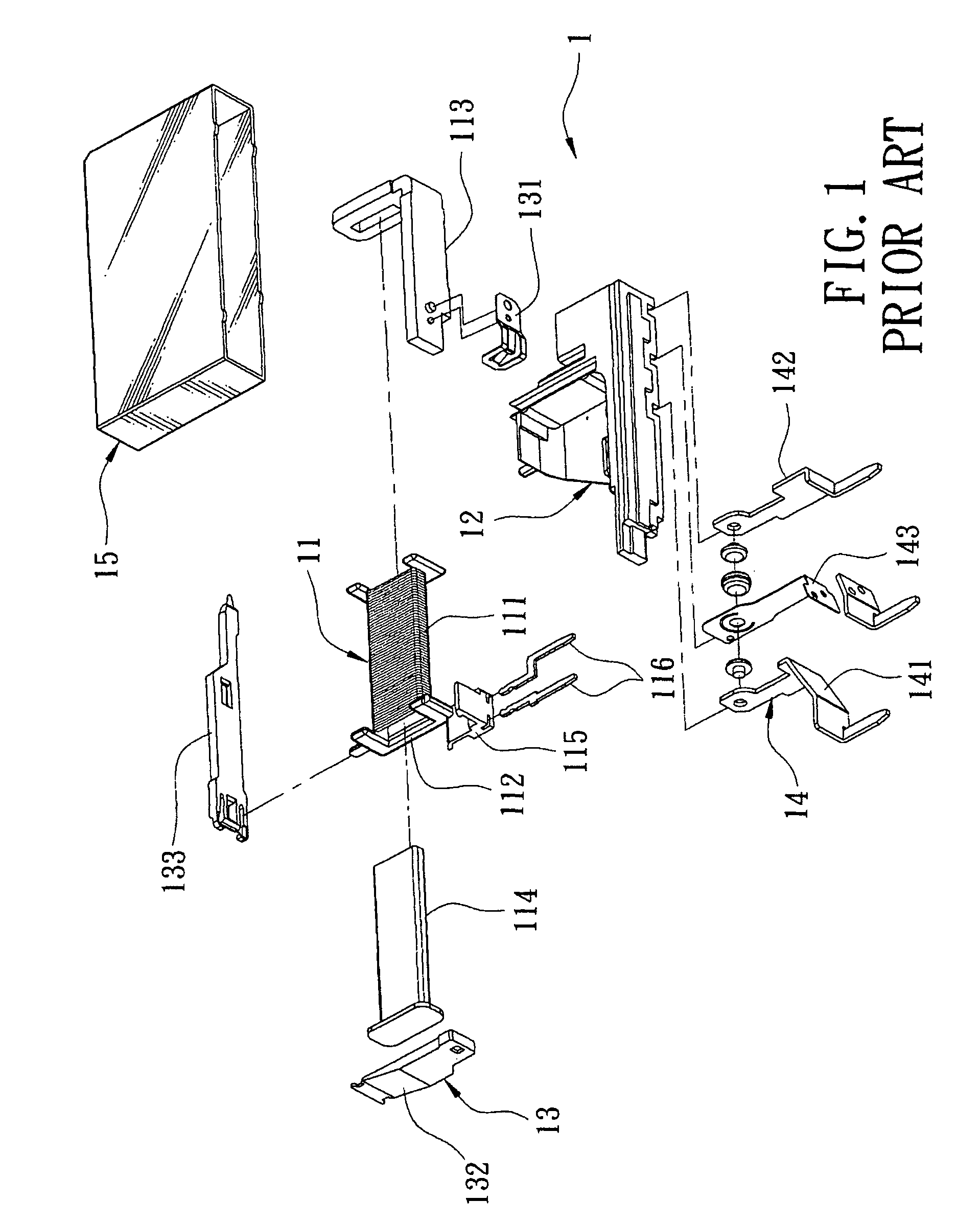
Second, riveting of the resilient component 131 on the yoke component 113, and improper positioning of the magnetic component 132 relative to the first mounting frame 112 result in complex and difficult assembly of the relay 1.
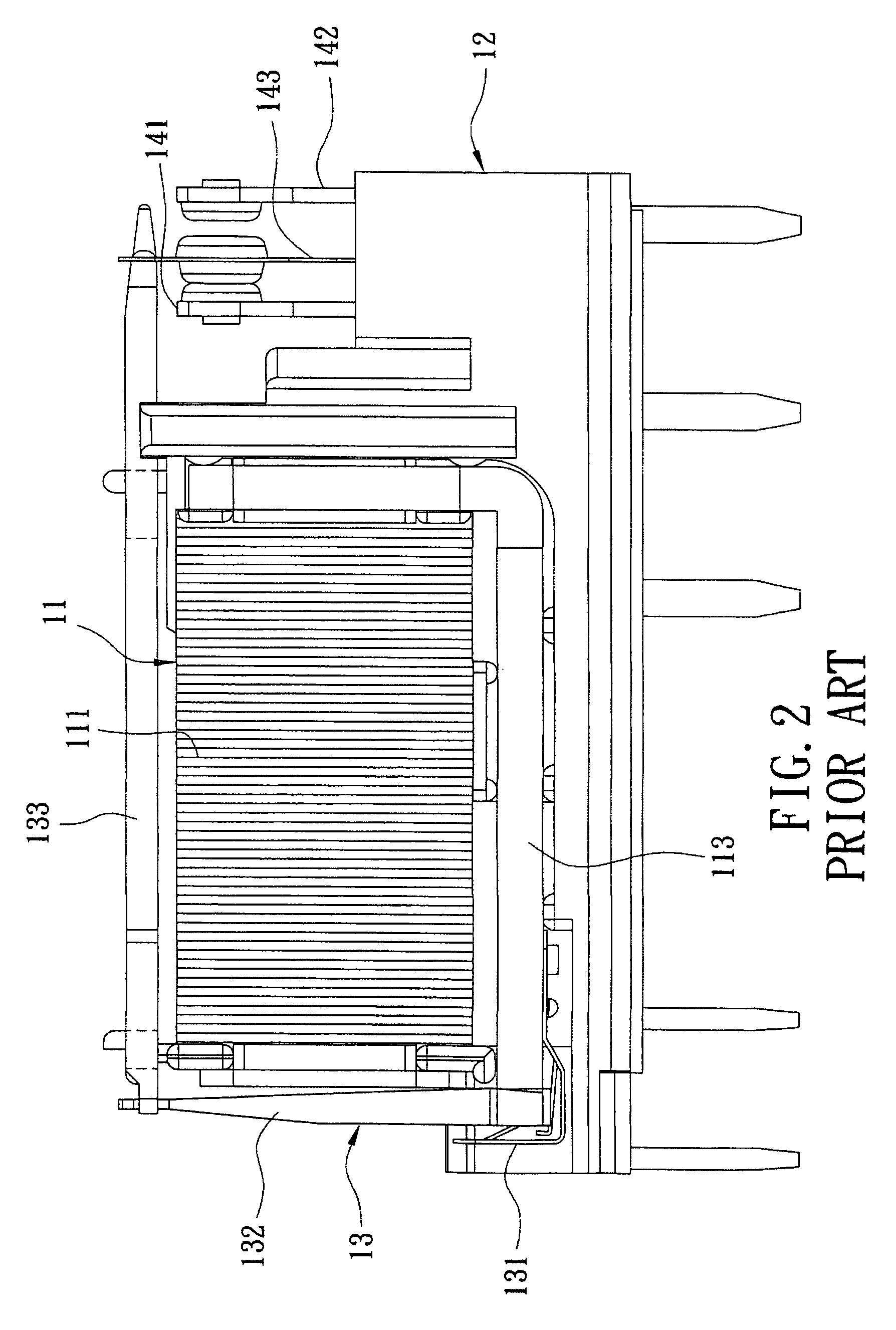
Moreover, the casing 12 has an open configuration such that the relay core member 11 of the conventional electromagnetic relay 1 cannot be electromagnetically isolated very well, and is susceptible to interference from the surroundings.
Further, assembly accuracy is relatively poor due to the open configuration of the casing 12 such that the conventional electromagnetic relay 1 has a relatively lower breakdown voltage value.

Method used


Image

  • Electromagnetic relay
  • Electromagnetic relay
  • Electromagnetic relay

Examples


Embodiment Construction

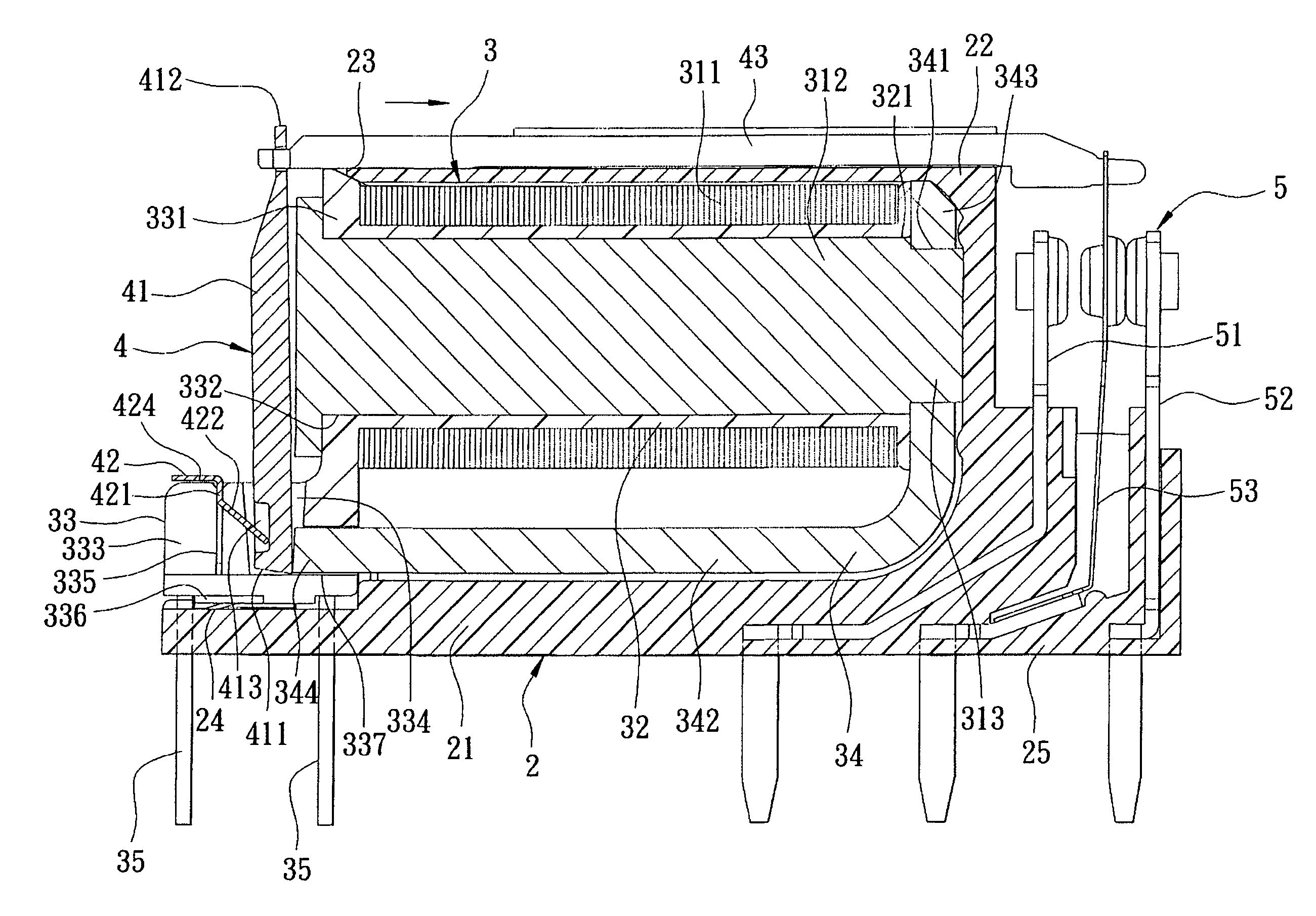
[0020]Referring to FIG. 3, an electromagnetic relay of the preferred embodiment includes a casing 2, a relay core member 3, an actuating set 4, a terminal set 5 and a housing 6.

[0021]Referring to FIGS. 3 to 6, the casing 2 has an opening 23 (see FIG. 5), and includes an elongate bottom plate 21, a block-engaging unit 24 formed with two engaging grooves 241 (only one is shown in FIG. 3) and disposed on an end of the bottom plate 21 proximate to the opening 23, a terminal-mounting unit 25 disposed on an opposite end of the bottom plate 21 for mounting the terminal set 5, and a casing body 22 disposed on an intermediate position of the bottom plate 21 and formed with the opening 23.

[0022]The relay core member 3 is adapted for generating an electromagnetic field, and includes a coil unit 31, a first mounting frame 32 for mounting the coil unit 31 thereon and disposed within the casing 2, a second mounting frame 33 connected fixedly to the first mounting frame 32 for sealing the opening ...


PUM


Abstract

An electromagnetic relay includes: a casing formed with an opening; a relay core member adapted for generating an electromagnetic field and inserted into the casing through the opening; an actuating set that is inserted into the relay core member, that is exposed from the casing, and that can be driven by a magnetic attraction force attributed to the electromagnetic field; a terminal set disposed on the casing and adapted to be actuated by the actuating set to thereby act as a switch mechanism; and a housing accommodating the casing, the relay core member, the actuating set and the terminal set.

Description

CROSS-REFERENCE TO RELATED APPLICATION[0001]This application claims priority of Taiwanese Application No. 097143683, filed on Nov. 12, 2008.BACKGROUND OF THE INVENTION[0002]1. Field of the Invention[0003]The present invention relates to an electromagnetic relay, more particularly to an electromagnetic relay that is easy to assemble accurately and has a relatively higher breakdown voltage value.[0004]2. Description of the Related Art[0005]Referring to FIGS. 1 and 2, a conventional electromagnetic relay 1 includes a relay core member 11, a casing 12 for mounting of the relay core member 11, an actuating set 13, a terminal set 14, and a housing 15 for accommodating the relay core member 11, the casing 12, the actuating set 13 and the terminal set 14. The relay core member 11 includes a first mounting frame 112, a coil 111 wound around the first mounting frame 112, a yoke component 113 abutting against two adjacent sides of the coil 111, a magnetic core 114 extending through the coil 11...

Claims


Application Information

Patent Timeline
Patent Type & Authority Patents(United States)
IPC IPC(8): H01H51/22
CPCH01H50/026H01H50/042H01H50/26H01H50/28H01H50/642H01H2050/028H01H2050/046H01H2050/367H01H2050/446
Inventor KUO, MING-CHANG
Owner EXCEL CELL ELECTRONICS
Learn More