Crossbow stock having lower floating rail

a technology of floating rails and crossbows, which is applied in the field of crossbows, can solve the problems of inapplicability of the techniques used by firearm makers to isolate the heat of the barrel from the user's hands and/or accessories, and the difficulty of achieving the effect of reducing the effect of the firing characteristics of the crossbow

Active Publication Date: 2011-08-16
PRECISION SHOOTING EQUIP
View PDF15 Cites 76 Cited by
  • Summary
  • Abstract
  • Description
  • Claims
  • Application Information

AI Technical Summary

Benefits of technology

[0019]The support rail is adapted to assist the user in supporting the crossbow during release of the bowstring. For example, a right-handed user may grasp the support rail directly with the user's left hand. On the other hand, one or more support members, such as a fore-grip member, may be secured along the support rail, and the user may grasp one of such fore-grip members to help steady the crossbow during firing. Alternatively, a support member in the form of a bi-pod may be secured along the support rail to help steady the crossbow during firing. Optionally, the support rail can be rested upon a sandbag or other stable support structure to help steady the crossbow during firing. Preferably, the support rail is configured so that such accessory support members can slide over, and clamp onto, the support rail. In any of these cases, since the support rail is always secured to the same point on the elongated frame member of the crossbow, variations in the positioning of the user's forward hand, fore-grip, bi-pod, sandbag, etc., along the support rail minimize the effect on the firing characteristics of the crossbow.
[0020]In the preferred embodiment of the invention, the aforementioned support rail is formed integrally as one piece with the elongated frame member. Preferably, the support rail is formed as a so-called “Picatinny rail”, generally corresponding to MIL-STD-1913, and having a generally T-shaped cross-section, including a series of ridges interspersed with flat spacing slots. The Picatinny rail provides a standardized mounting platform, onto which fore-grips, bi-pods, or other accessories may easily be secured, as by sliding and clamping such items onto the support rail.

Problems solved by technology

While there are some hunters own both a rifle and a crossbow, experienced hunters accustomed to hunting with rifles do not often branch into the use of crossbows, perhaps because they perceive that crossbows are too complex to operate.
However, Applicants have found that the increasing arrow speeds, and extended shot distances, produced by state-of-the-art crossbows effectively multiply the impact of such subtle variations in the support of the crossbow, thereby introducing noticeable errors in shot placement from one shot to the next.
Thus, in the case of crossbows, there is no need to isolate heat from the user's hands or from sensitive optics, and techniques used by firearm makers to isolate the heat of the barrel from a user's hands and / or accessories are not applicable.
Moreover, until recently, crossbow firing speeds, shooting distances, and general accuracy, were all so limited that variations in the placement of the user's hands on the crossbow, or variations in the manner in which the crossbow was supported by a sandbag, bi-pod, or the like, were relatively insignificant.

Method used


Image

  • Crossbow stock having lower floating rail
  • Crossbow stock having lower floating rail
  • Crossbow stock having lower floating rail

Examples


Embodiment Construction

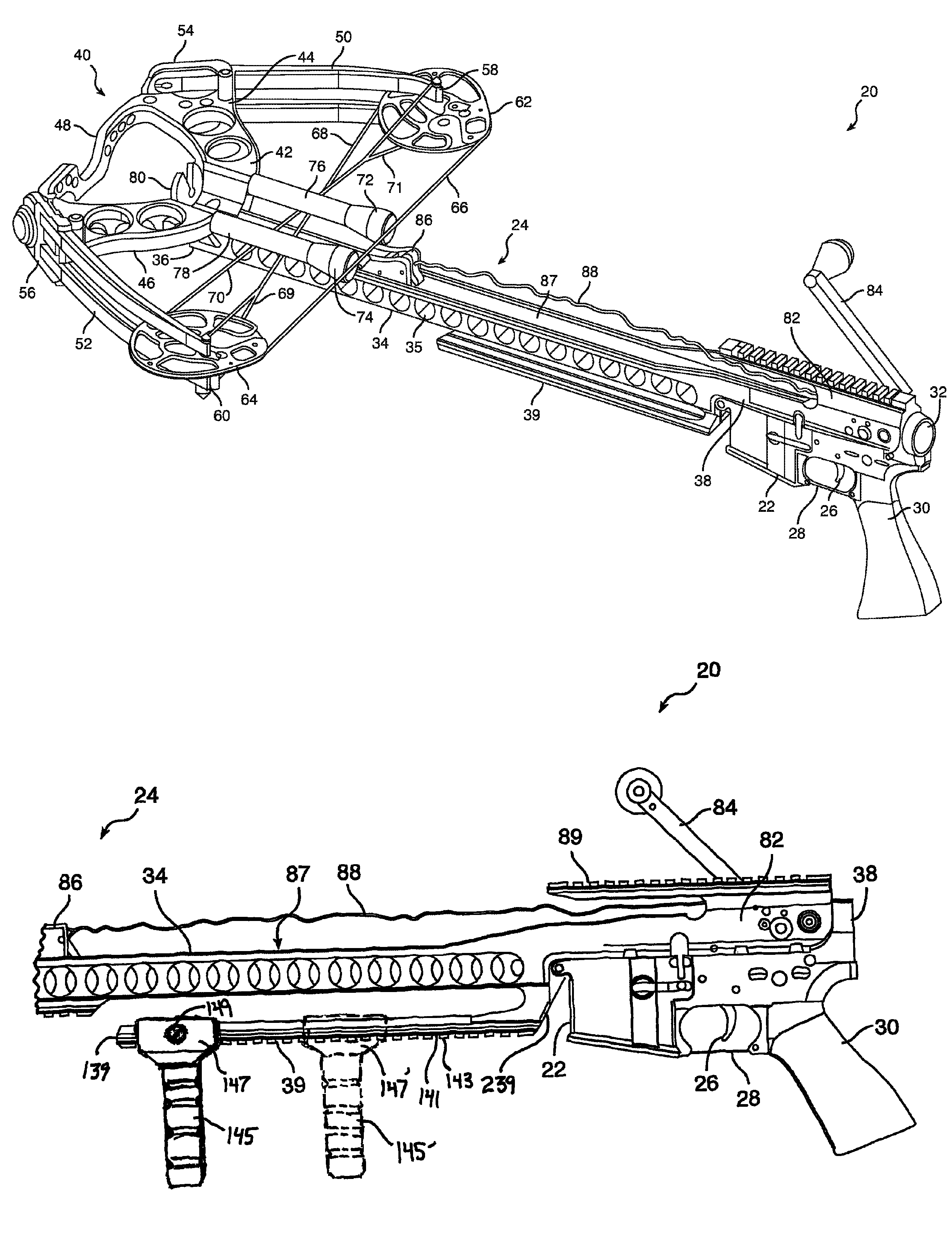
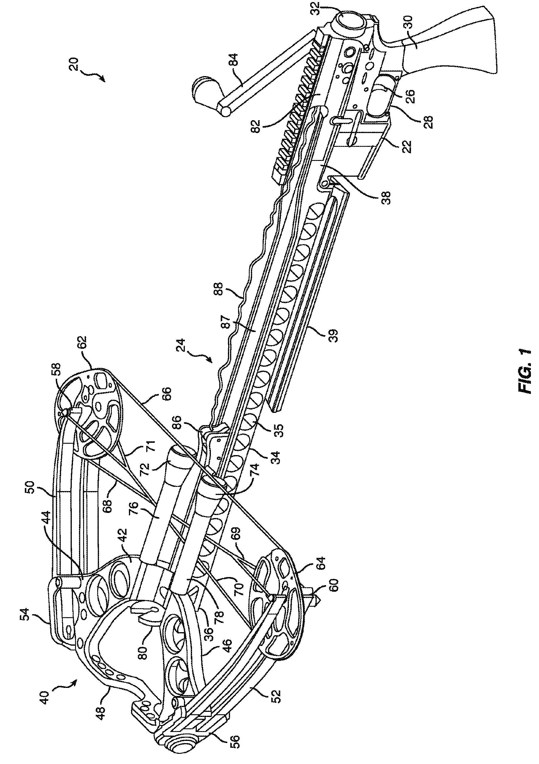
[0043]FIG. 1 shows a crossbow, designated generally by reference numeral 20, and including the modular lower receiver 22 of an AR-15 style rifle attached to crossbow accessory 24. While the preferred embodiment uses an AR-15 style lower receiver 22, those skilled in the art will appreciate that the lower receivers of other models of rifles may also be used. In addition, while the described embodiment is a crossbow accessory for an existing lower receiver already owned by a user, those skilled in the art will appreciate that the described crossbow assembly may integrally incorporate the components of such lower receiver into the crossbow if desired.

[0044]As is known to gun enthusiasts, lower receiver 22 includes a finger trigger 26 which extends downwardly from the housing of lower receiver 22. A trigger guard 28 may also be included. A pistol grip 30 is also preferably provided along with lower receiver 22. The rear end of lower receiver 22 includes a threaded opening 32 adapted to ...


PUM


Abstract

A crossbow has a riser, flexible limbs, a bowstring extending between the tips of the limbs for propelling an arrow, and an elongated frame extending from the riser. A bowstring release proximate the rear end of the elongated frame includes a trigger for releasing the bowstring, and firing an arrow. A first grip is disposed proximate to the trigger for being grasped by the user's first hand. A “Picatinny” type support rail extends along and below the elongated frame, secured at its rearmost end to the elongated frame, but otherwise spaced therefrom. The support rail can receive fore-grips, a bi-pod, or can be rested against a support surface to help steady the crossbow during firing.

Description

CROSS-REFERENCE TO RELATED APPLICATIONS[0001]The present application is a continuation-in-part of co-pending non-provisional U.S. patent application Ser. No. 12 / 350,106, filed on Jan. 7, 2009, entitled “Crossbow Accessory for Lower Receiver of Rifle and Related Method”, assigned to the assignee of the present application, and the benefit of such earlier filing date is hereby claimed under 35 U.S.C. §120.[0002]The present application is also related to co-pending application Ser. No. 12 / 350,123, filed on Jan. 7, 2009, and entitled “Release Assembly for Crossbow”, assigned to the assignee of the present application.[0003]The present application is related to a co-pending application Ser. No. 12 / 350,131, filed on Jan. 7, 2009, and entitled “Compact Winding Mechanism for Crossbow”, assigned to the assignee of the present application.BACKGROUND OF THE INVENTION[0004]1. Field of the Invention[0005]The present invention relates generally to crossbows, and more specifically, to a crossbow h...

Claims


Application Information

Patent Timeline
Patent Type & Authority Patents(United States)
IPC IPC(8): F41B5/12
CPCF41B5/12F41B5/1469
Inventor SHEPLEY, PAUL EDWINHANSEN, KEVINRASOR, JR., ALLEN C.KRONENGOLD, DAVID H.
Owner PRECISION SHOOTING EQUIP
Why Eureka
Try Eureka