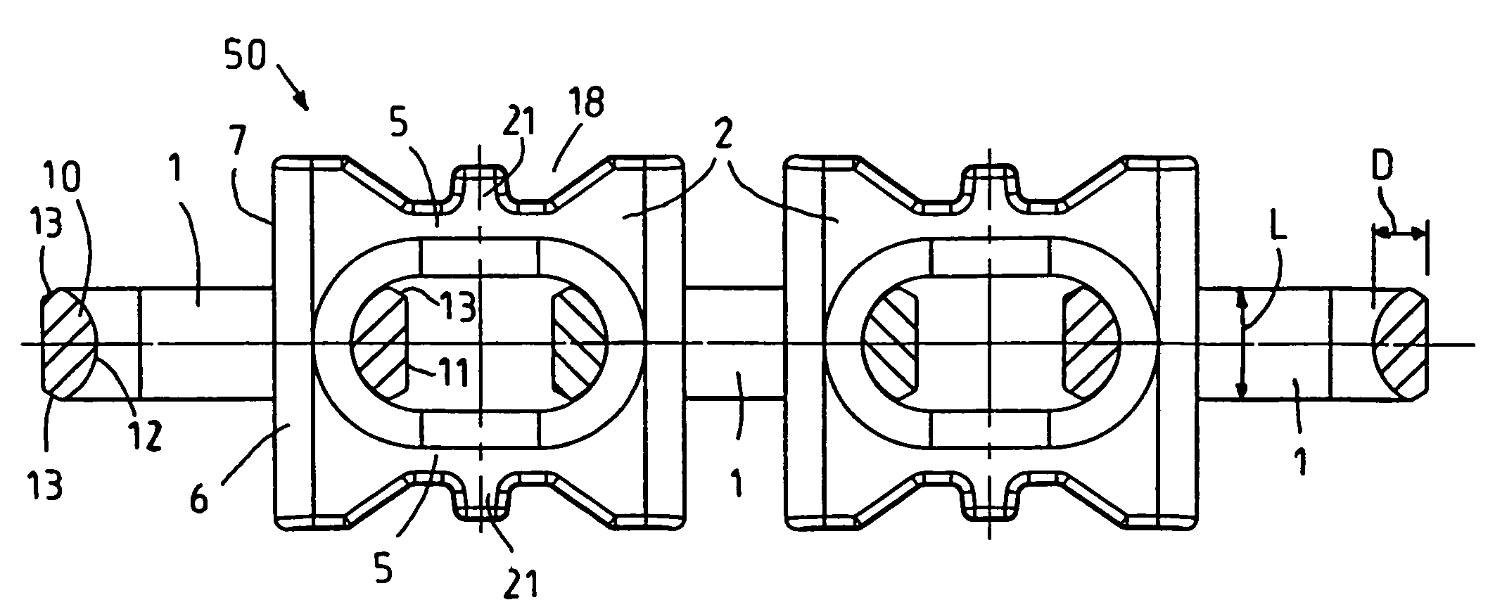
[0007]An object of the invention is to create a high-strength link chain for use in particular in the case of scraper chain conveyors which can even be easily used in the case of large lengths of several hundred meters without being dimensioned overproportionally in terms of their height and in terms of their weight and which are also characterized by good load and running characteristics of the horizontal and vertical chain links with one another and during passing through of the chain wheel, and which also enables good mounting of scrapers and entrainment of the mounted scrapers.
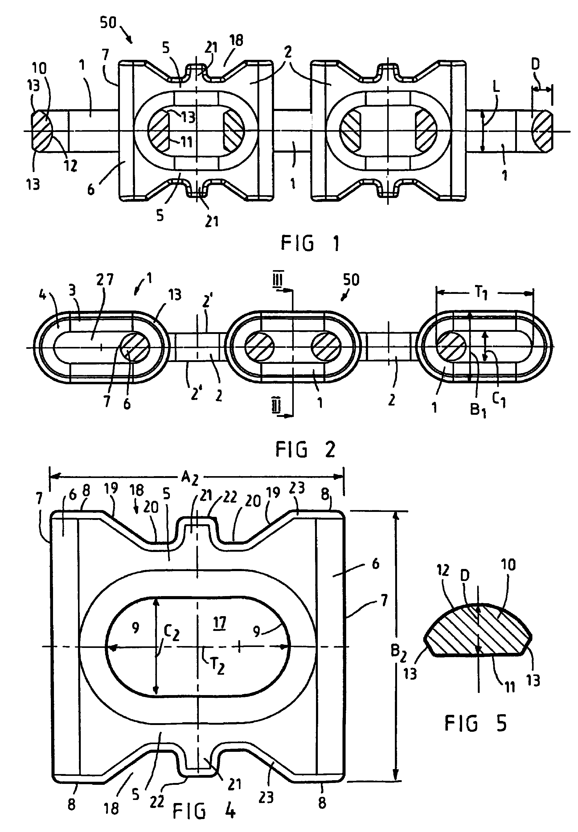
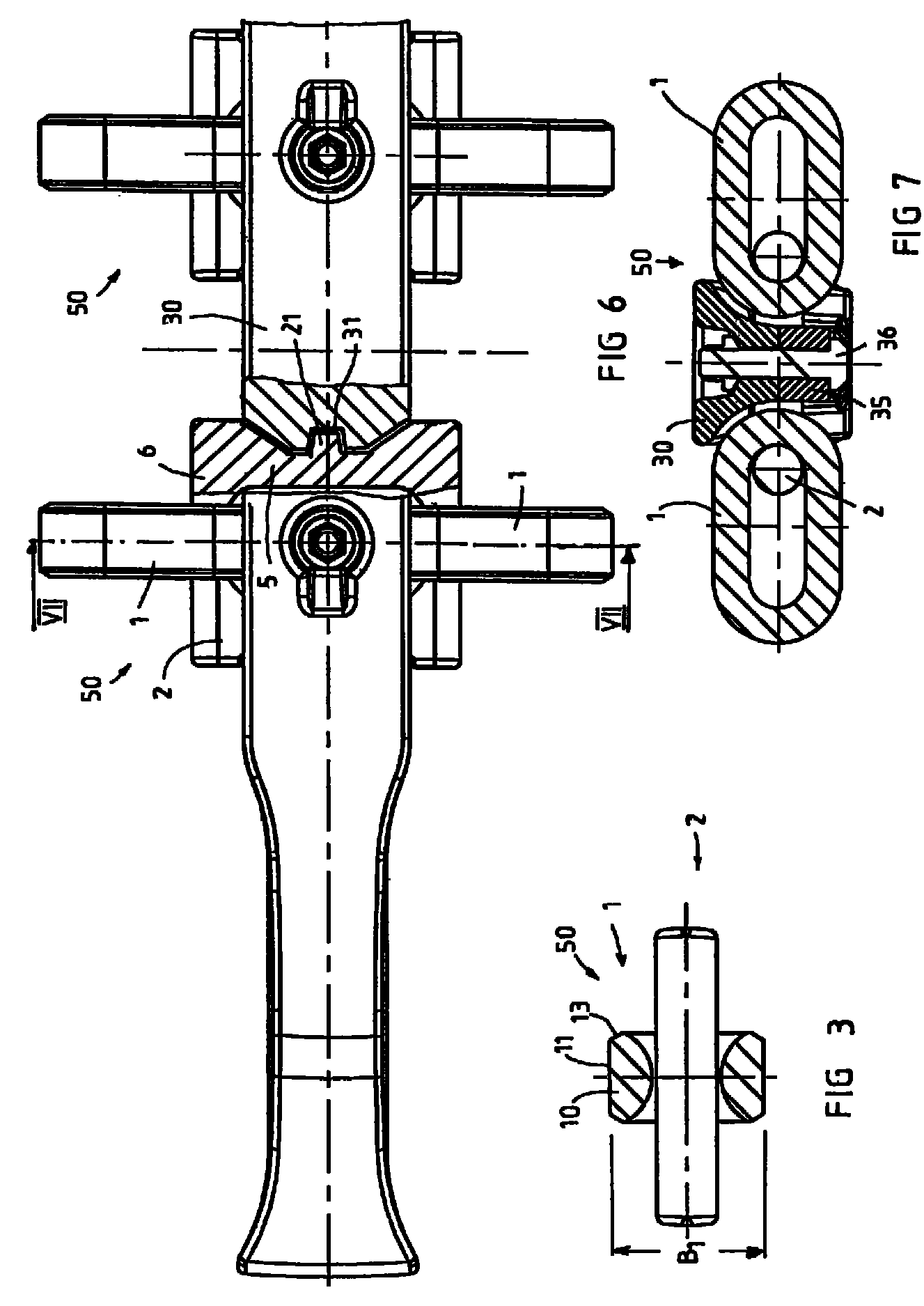
[0008]According to a further aspect of the invention, the link chain includes a horizontal chain link wherein the horizontal chain links have, on both sides in the recesses, entrainment means for positive-locking entrainment of scrapers which can be connected to the horizontal chain links and / or the cross-sectional profile of the vertical chain links is in each case provided with a bevel at the transition of the flat section into the circular arc. As a result of the entrainment means formed according to the invention in the recesses, extremely good entrainment characteristics are achieved for the scrapers connected to these horizontal chain links without it being necessary to produce special chain links, in particular web chain links, and enclosing them in the link chain at a specific position. The straight face side present in the case of the horizontal chain links at the front sections enables significantly smaller surface pressures between the front faces of the horizontal chain links and a chain wheel in comparison to other chain link geometries even if the bearing surface available for bearing is smaller than in the starting status due to signs of wear on the pockets of the chain wheel. The vertical chain links with the flat profiling forming in a rotary manner across its circumference, the circular arc-shaped camber on the inner surface facing the inner opening and the bevels at the transition of the flat section to the circular arc bring about significantly improved running characteristics of the link chain overall despite the still possible low overall height of the link chain since, as a result of the bevels at the transition to the outside of the vertical chain links, their angling capacity to the horizontal chain links in the interlinked state is improved. The bevels on the vertical chain links also enable that the link chain is overall better adjusted at the chain wheel to the pockets for the horizontal chain links and the gaps for the vertical chain links since the bevels can assume a threading function for the vertical chain links at the tooth gaps. The cooperation of the innovations according to the invention on the horizontal chain links and on the vertical chain links significantly improves the running characteristics and wear characteristics of a link chain according to the invention. However, both measures are also of independent inventive importance.
[0009]According to another aspect of the invention, the bevel on the horizontal chain links runs relative to the flat section at an angle of approximately 60°±2°. It is furthermore advantageous if the cross-sectional profile of the vertical chain links has a width to thickness ratio of width L to thickness D of L / D≧2. The corresponding cross-sectional profile enables very flat-design vertical chain links which simultaneously possess a sufficient cross-sectional surface to be able to withstand the large forces during operation of the link chain. At the same time, the vertical chain links can furthermore be produced relatively simply and cheaply from rolled profile rods with correspondingly larger diameters for the high power requirement of a conveyor of e.g. 42 mm in the usual welded design. In the case of the link chain according to the invention, the clear inner width of the inner openings of the horizontal chain links is preferably significantly larger than the clear inner width of the vertical chain links.
[0010]According to yet another aspect of the invention, the entrainment means are formed centrally between both front sections such that overall a symmetrical horizontal chain link is created which has no preferred direction during installation in a link chain and during operation. In the case of one embodiment, each entrainment means protrudes into associated recess on the side flanks of the otherwise approximately rectangular horizontal chain links in a projecting manner such that no weakening of the longitudinal limbs of the horizontal chain links and thus no weakening of the supporting profile cross-section of the horizontal chain links can occur as a result of the entrainment means. The entrainment means can in particular comprise a projecting web which extends over the entire depth of the longitudinal limbs of the horizontal chain links such that the entrainment means then have an even and large active surface in cooperation with scrapers fixed thereon. In operational use, the entrainment means bring about that the scrapers are moved in a pushing manner with the link chain, wherein the two-sided support of the scrapers by the entrainment means formed on both sides generates an even entrainment behavior of the scrapers. It is particularly advantageous if the entrainment means is an entrainment nose formed on the longitudinal limb with a preferably trapezoidal cross-section.
[0011]According to a further embodiment, the free end faces of the entrainment means can have a shorter distance from one another than the outer width of the front sections such that the entrainment means of horizontal chain links to which no scraper is connected in operational use lie in the direction of movement in the protected region behind the outer corners of the straight front sections of the horizontal chain links. In one embodiment of the horizontal chain links, the origin of the recesses on the front sections is spaced apart from the straight front zones of the front sections and / or a preferably straight intermediate portion is formed between the origin and the front zone. As a result of these measures, the front corner regions of the front sections are additionally reinforced over the known configuration of the horizontal chain links and the risk of excess wear on the lateral delimiting faces of the front sections is minimized. Moreover, as a result of this shaping, the active bearing face of the horizontal chain links on the pockets of the chain wheel increases again and the surface pressures in operational use are further reduced. Moreover, the recesses can preferably have two flanks beveled in a straight line which preferably enclose an angle of approximately 110°±4°. The recesses are thus significantly more pronounced in the case of the horizontal chain links according to the invention than in the case of those known from the prior art, as a result of which the available bearing surface between the horizontal chain links and the scrapers connected to these is simultaneously increased. It is advantageous if a base section which is straight up to the projecting entrainment means is formed in the region of the recesses between the flanks.
[0013]The feed characteristics of the link chain according to yet another aspect of the invention is provided wherein in the case of a chain wheel, the tooth side walls delimiting the gap are likewise provided with a bevel at the transition to the circumferential wall surface of the tooth elements. The bevels on the tooth side walls can cooperate particularly advantageously with the bevels on the vertical chain links and significantly improve the threading of the vertical chain links into the gaps and thus also of the following horizontal chain links into the respective pockets. It is apparent that, in the case of a chain wheel, several toothed rings, in particular three toothed rings, can be present next to one another, of which one central toothed ring is formed as a double tooth element in order to be able to drive and move a double center chain with the chain wheel. It is also advantageous in the case of the chain wheel according to the invention if the bevels run relative to the circumferential wall surface at an angle of approximately 60°±2°. Moreover, the distance between the tooth side walls of adjacent rings can increase continuously from the chain wheel base to the circumferential face or to the origin of the bevel at the tooth elements in order to further improve the feed characteristics of the vertical chain links into the tooth gaps.


