Lamp having plurality of optical extraction structures

a technology of optical extraction and lampshade, which is applied in the field of lamps for emitting light, can solve the problems of less defined direction of emitted light, and achieve the effect of enhancing the brightness of the lamp and broadening the range of effects availabl

Inactive Publication Date: 2011-08-16
SIGNIFY HLDG BV
View PDF13 Cites 4 Cited by
  • Summary
  • Abstract
  • Description
  • Claims
  • Application Information

AI Technical Summary

Benefits of technology

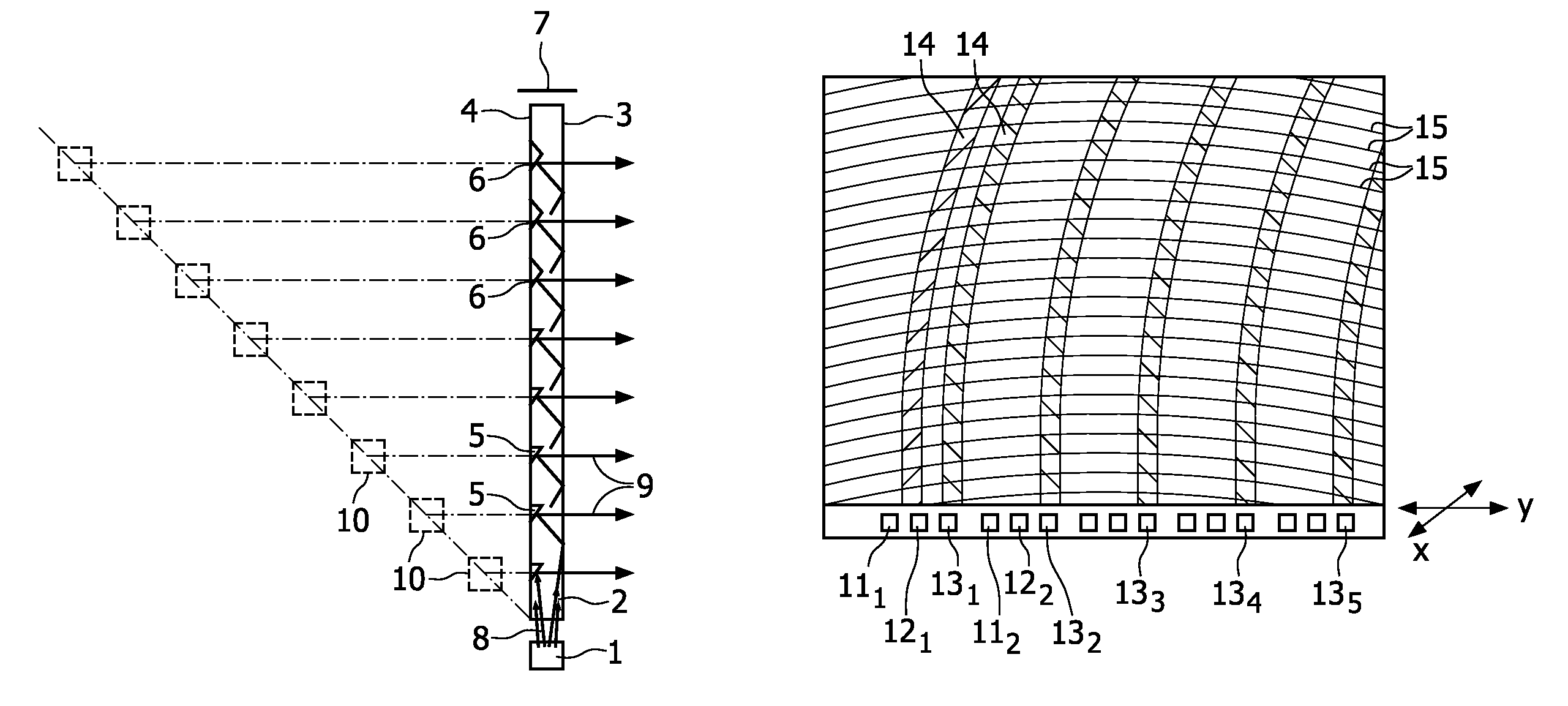
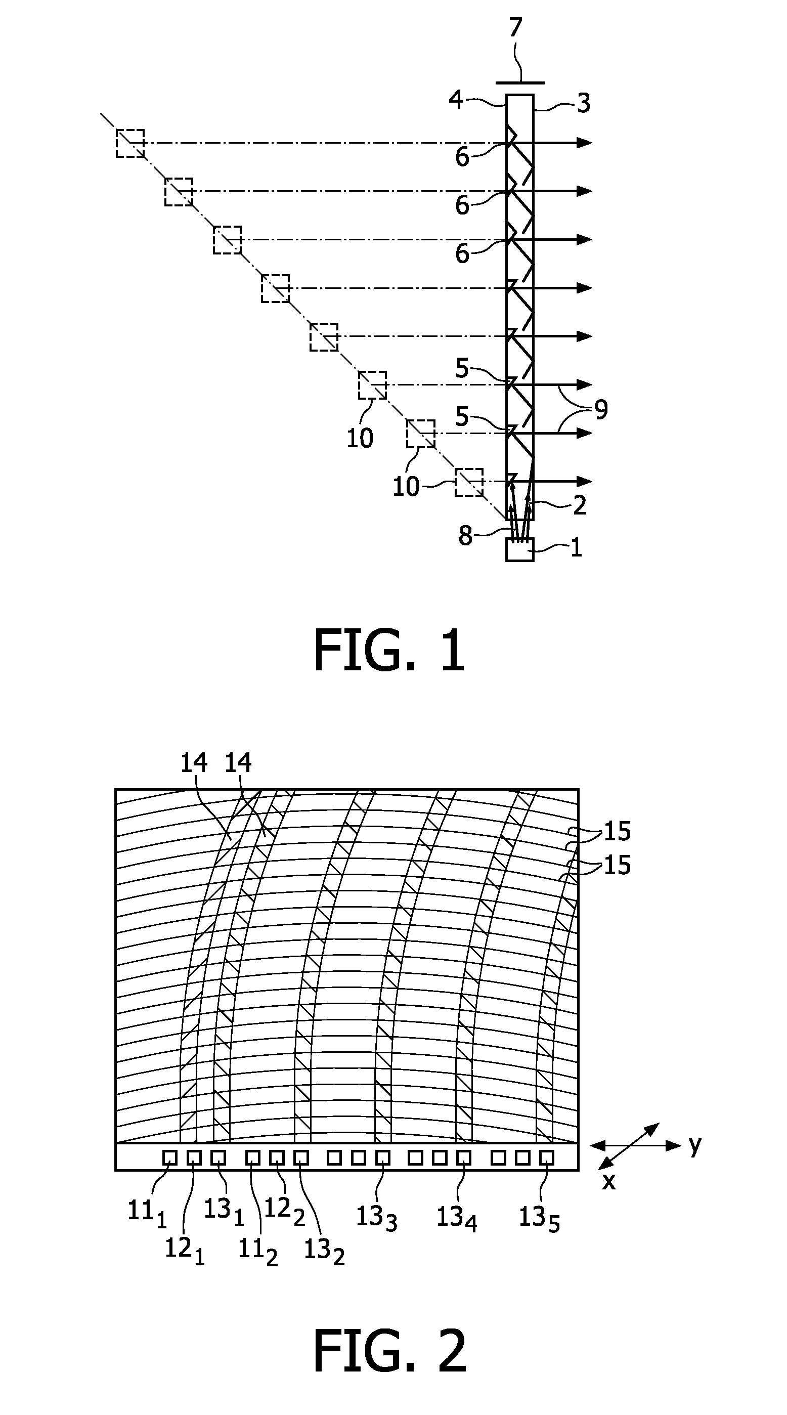
[0010]In a special embodiment, the extraction structures are mutually separated by a distance of at least 2 mm, preferably at least 5 mm. This relates to a special effect that was discovered by the inventors. When looking at the lamp, the extraction structures, i.e. for example the mirroring surfaces, will reflect the light from the light sources. This will cause a virtual image of each of the light sources to be made for every extraction structure. These images will have an intensity that depends on the dimensions of the extraction structure, e.g. an intensity that diminishes away from the real light sources, if the extraction surfaces are all equal. A more important effect as found by the inventors is that, especially when looking at the lamp at a non-zero angle with respect to a plane perpendicular to the array of light sources (e.g. if the array of light sources are at the lower side of the lamp, when looking from the sides), the virtual images of the light sources seem to “run off” into the distance. This means that, the further the viewer is from the real light sources, the deeper into the lamp the virtual images are perceived. This means that the flat lamp has a perceived depth. This 3D-effect may be observed because the light as extracted by the extraction structures is well-defined. The individual images of the light sources would be blurred into one mass of light if the lamp were to comprise light scattering means, or irregular extraction surfaces et cetera. Now, with the above mutual distance between the extraction structures, it is easily possible for the viewer to separate the separate virtual images. If the virtual images were too close together, they would coalesce into a single light field, which would suppress the 3D-effect.
[0038]Other possible uses include the use in a building where e.g. only a small space is available. Because of the 3D effect, the impression of a larger room may be given by the flat lamp according to the invention.

Problems solved by technology

However, a disadvantage of such backlights, or lamps of this kind in general, is that the direction of the emitted light is much less well-defined.

Method used


Image

  • Lamp having plurality of optical extraction structures
  • Lamp having plurality of optical extraction structures
  • Lamp having plurality of optical extraction structures

Examples


Embodiment Construction

[0048]FIG. 1 very diagrammatically shows a lamp according to the invention, in a cross-sectional side view, with a 3D appearance.

[0049]Herein, 1 denotes an LED and 2 a lightguide with a front surface 3 and a back surface 4. In the lightguide there are a plurality of extraction structures 5 and 6. A mirror is denoted with reference numeral 7.

[0050]LED 1 emits a (narrow) bundle of light 8 that enters the lightguide 2. The light is guided by total internal reflection at the front surface 3 and the back surface 4. If necessary, the light is reflected back by mirror 7.

[0051]A part of the light will be incident on the extraction structures 5, either directly or after a number of reflections, as partly indicated by dashed lines. The extraction structures 5 are recesses that are e.g. machined into the lightguide, and that comprise a reflection surface at an angle e.g. between 30 and 50°. The light that is incident on the extraction surfaces is reflected to the front surface 3 and is able to...


PUM


Abstract

A lamp for emitting light, comprising a transparent sheet-like lightguide, with at least one light receiving side, a light emission front surface and a back surface opposite the front surface. The lamp further comprises a plurality of light sources, positioned in an array and optically coupled to at least one light receiving side. The back surface of said lamp comprises a plurality of optical extraction structures, for example provided in parallel curved lines. Furthermore, the lamp is substantially free from light scattering structures in a light path of the light to be emitted.

Description

[0001]This application is a national stage application under 35 U.S.C. §371 of International Application No. PCT / IB2007 / 054046 filed on Oct. 5, 2007, which claims priority to European Application No. 06121985.3, filed on Oct. 9, 2006, incorporated herein by reference.FIELD OF THE INVENTION[0002]The invention relates in general to a lamp. In particular, the invention relates in a first aspect to a lamp for emitting light, comprising a transparent sheet-like lightguide, with at least one light receiving side, a light emission front surface and a back surface opposite the front surface, and a plurality of light sources, positioned in a linear array and adjacent at least one light receiving side, wherein the back surface comprises a plurality of reflective optical extraction structures.BACKGROUND OF THE INVENTION[0003]So-called backlights of e.g. liquid crystal displays generally have a similar construction, comprising a side-lit lightguide, and extraction features to extract the light ...

Claims


Application Information

Patent Timeline
Patent Type & Authority Patents(United States)
IPC IPC(8): F21V7/04
CPCG02B6/0068G02B6/0038
Inventor CORNELISSEN, HUGO JOHANVAN DELDEN, MARTINUS HERMANUS WILHELMUS MARIA
Owner SIGNIFY HLDG BV
Why Eureka
Try Eureka