
Shieled connector having leveling arrangement ensuring reliable interconnection

a leveling arrangement and shield connector technology, applied in the direction of coupling device details, coupling device connection, shielding/protective earth/shielding arrangement, etc., can solve the problems of affecting the stability of shield joints and being vulnerable to breakag

Active Publication Date: 2011-08-16
HON HAI PRECISION IND CO LTD
View PDF6 Cites 9 Cited by
  • Summary
  • Abstract
  • Description
  • Claims
  • Application Information

AI Technical Summary

Benefits of technology

[0007]An object of the present invention is to provide a low profile shield connector steadily mounted to and properly supported on a PCB so as to ensure reliable interconnection thereof.

Problems solved by technology

Once excessive mating force or inadvertently downward force is applied, those solder joints are under jeopardy and vulnerable to break apart.

Method used


Image

  • Shieled connector having leveling arrangement ensuring reliable interconnection
  • Shieled connector having leveling arrangement ensuring reliable interconnection
  • Shieled connector having leveling arrangement ensuring reliable interconnection

Examples


Embodiment Construction

[0016]Reference will now be made to the drawing figures to describe the preferred embodiment of the present invention in detail.

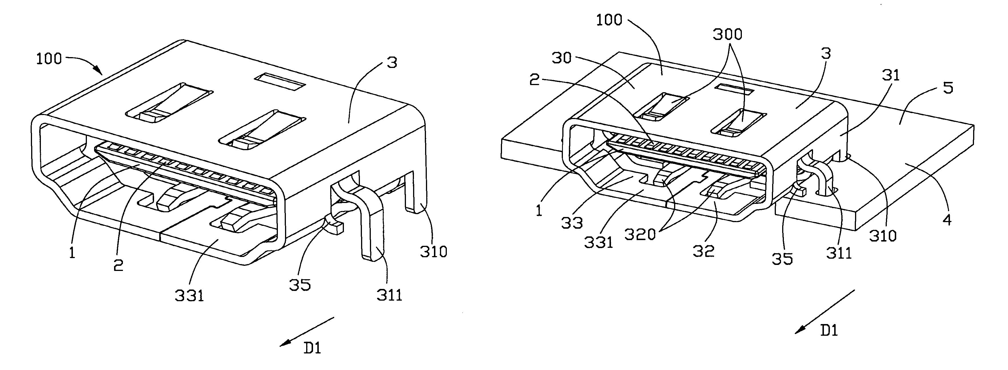
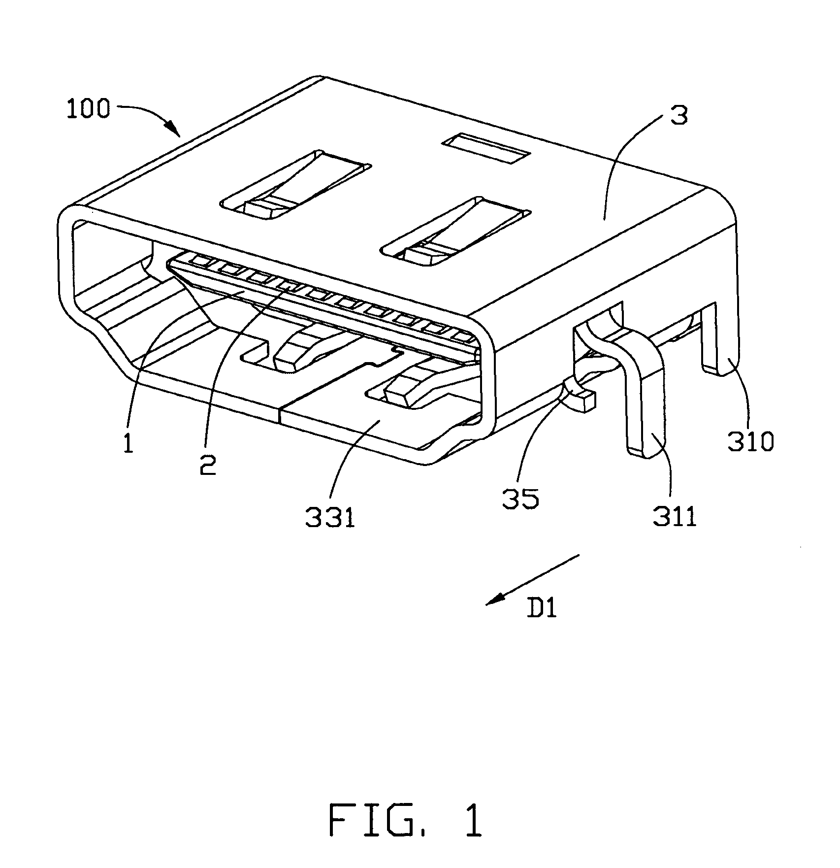
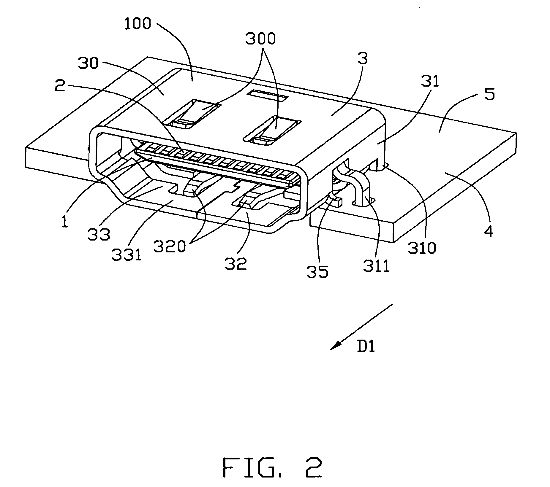
[0017]Referring to FIGS. 1 and 2, a shield connector 100 in accordance with the present invention is a low profile connector in which the connector is spanned over an opening of a printed circuit board (PCB) 4 such that the lower portion of the connector is coplanar to a low surface of the PCB 4 so as to reduce the overall height above the PCB 4. The shield connector includes an insulative housing 1 with a plurality of contact terminals 2 assembled therein and a metallic shell 3 surrounding the insulative housing 1.

[0018]Referring to FIGS. 3 to 5, the insulative housing defines a body portion 10, an engaging portion 11 extending from the body portion 10 and a plurality of receiving grooves 110 extending through the body portion 10 and the engaging portion 11 along a rear-to-front direction (i.e. mating direction) as marked by arrow D1. The contact terminals...


PUM


Abstract

A shield connector (100) includes a metallic shell (3) with a mating port (331) in communication with a mating receptacle with a tongue having a plurality of contact terminals (2) thereon. The contact terminals (2) include a plurality of solder tails (213, 223) extending out of the metallic shell (3). The metallic shell (3) defines a level arrangement (35) adjacent to the mating port (331) and defining a supporting plane coplanar to a mounting interface (5) of the shield connector (100).

Description

BACKGROUND OF THE INVENTION[0001]1. Field of the Invention[0002]The present invention relates to a shield connector, and more particularly to a shield connector having leveling arrangement ensuring reliable interconnection as well as mating capability.[0003]2. Description of the Related Art[0004]Nowadays, more and more electrical connectors has been designed so as to partially sunk into an opening of a printed circuit board (PCB) so as to meet the miniature trend. US Pat. Publication No. 2009 / 0130870 submitted by Wu et al. on Sep. 30, 2008, discloses a common sunk-typed connector mounted to a PCB for low profile. The connector includes an insulative housing, a plurality of contacts received in the housing and a metallic shell shielding insulative housing. The metallic shell is folded from a single sheet of metal so as to include a top wall, a bottom wall interconnected to the top wall by a pair of side walls. Each of the contacts includes a soldering tail extending outside of the in...

Claims


Application Information

Patent Timeline
Patent Type & Authority Patents(United States)
IPC IPC(8): H01R13/648
CPCH01R12/7052H01R12/707H01R2107/00
Inventor XU, FENG
Owner HON HAI PRECISION IND CO LTD
Learn More