Medical connector

a technology of medical connectors and connectors, which is applied in the direction of tube connectors, valves, other medical devices, etc., can solve the problems of difficult to retrieve male luer caps, increase the risk of unsanitary conditions inside and outside of the fluid transfer system, and the fluid in the tubing and connectors can be harmful if released

Active Publication Date: 2011-08-16
ICU MEDICAL INC
View PDF240 Cites 127 Cited by
  • Summary
  • Abstract
  • Description
  • Claims
  • Application Information

AI Technical Summary

Benefits of technology

[0016]Another embodiment that can prevent the decoupling of the female portion of the male luer connector from the corresponding male connecting portion of the coupled component is described herein. In brief, without limitation, this embodiment of a luer connector can comprise a rigid housing having a first end and a second end. The housing further can comprise a rigid tubular male portion at a first end, a rigid tubular female portion comprising a breakaway arrangement at a second end, and a longitudinal opening therethrough. The male portion can be configured to be engageable with a female connector. The female portion can be configured to be engageable with a male connector. The breakaway arrangement can substantially prevent the removal of the corresponding male connector portion of the coupled component from the female portion of the luer connector.
[0018]In some embodiments, this is accomplished as follows. As will be described in greater detail below, the female portion of the luer connector can comprise an end cap between the main housing body and the female connector. The end cap can comprise a first end cap component and a second end cap component. The second end cap component can be supported by a housing member, and the first end cap component can be supported by the second end cap component and can be partially positioned on the inside of the second end cap component. The first end cap component of the luer connector can comprise one or more tabs protruding radially outwardly from an outside surface thereof that can engage with complementary tabs protruding radially inwardly from an inside surface of the second end cap component. In a first state, the engagement of the tabs can prevent the first end cap component of the luer connector from rotating freely within the second end cap component. The tabs protruding outwardly from the first end cap component of the luer connector can be configured to shear or break off when a predetermined level of torque is applied to the first end cap component of the luer connector, which, in some embodiments, can occur when a male luer portion of the coupled component is substantially fully threadably engaged with the first end cap component of the luer connector. Once the tabs on the first end cap component of the luer connector have sheared or broken off, the first end cap component of the luer connector then can rotate substantially freely within the second end cap component so that the male portion of the coupled component cannot be rotated relative to the first end cap component. In other words, when the male portion of the coupled component is rotated relative to the luer connector, the first end cap component can rotates in unison with the male portion of the coupled component so that the male portion of the coupled component is substantially prevented from decoupling from the first end cap component, hence, the luer connector.

Problems solved by technology

It is often a challenge to keep such systems sterile and to prevent leakage of fluids when the various components are engaged and disengaged.
Because such closure mechanisms are not automatic (or not used at all), male luer connectors are sometimes left unsealed, allowing fluid to drip out.
This may increase the risk of unsanitary conditions inside and outside of the fluid transfer system.
In addition, in some medical applications such as certain chemotherapy treatments, the fluids in the tubing and connectors can be harmful if released.
Moreover, in the busy environment of hospitals and other medical settings, health care providers must often quickly manipulate multiple medical implements with one hand, making it difficult to retrieve male luer caps and rapidly attach them upon disengagement of male connectors.

Method used


Image

  • Medical connector
  • Medical connector
  • Medical connector

Examples


Embodiment Construction

[0010]Disclosed are various embodiments of medical connectors with closeable male luers. It is contemplated that the features of the various embodiments disclosed herein are combinable to form additional embodiments. Such combinations are within the scope of this disclosure.

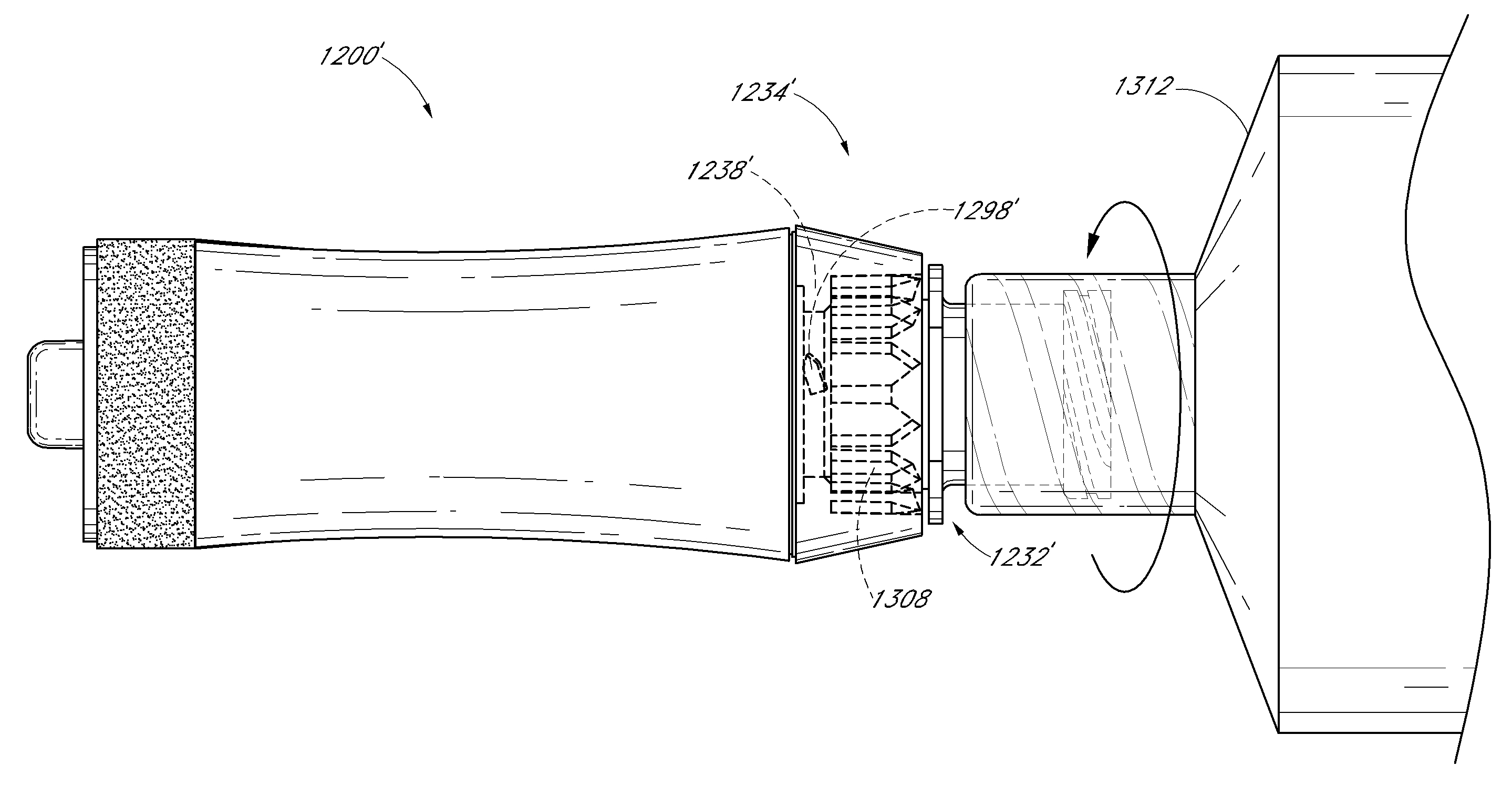
[0011]In an exemplary embodiment, a male luer connector has a main housing with first and second ends. The second end of the housing comprises a male luer and a shroud surrounding at least a portion of the male luer. The shroud has screw threads disposed on an internal wall thereof. A tubular valve member with a fluid pathway is disposed within the housing. The valve member has a tip on its second end. In the region near the tip, a pair of fluid holes is positioned on opposite sides of the valve member. The tip is configured to abut snugly against an internal wall of the male luer in a region at or near the second end of the male luer. The valve member also has a pair of struts directed towards the second end. Th...


PUM


Abstract

A luer connector including a rigid housing having a first end and a second end. The housing further including a rigid tubular male portion at the first end, a rigid tubular female portion at the second end, and a longitudinal opening therethrough. The male portion is configured to be engageable with a female connector. The female portion is configured to be engageable with a male connector and to prevent the disengagement of the male connector from the female portion. In some embodiments, the female portion is configured to maintain a fixed rotational position when the male connector is being threaded therewith, but to rotate with the male connector once the male connector has become fully engaged with the female portion so as to prevent the male connector from becoming unthreaded from the female portion.

Description

RELATED APPLICATIONS[0001]This application is related to and claims the benefit of U.S. Provisional Patent Application Nos. 60 / 938,428, filed on May 16, 2007, 60 / 978,697, filed on Oct. 9, 2007, and 61 / 042,016, filed Apr. 3, 2008, each of which is incorporated by reference in its entirety herein. This application also incorporates by reference in their entireties U.S. Provisional Patent Application No. 60 / 696,894, filed on Jul. 6, 2005, and to U.S. Provisional Patent Application No. 60 / 707,319, filed on Aug. 11, 2005, and U.S. patent application Ser. No. 11 / 417,604, filed on May 3, 2006 and Ser. No. 11 / 482,176, filed on Jul. 6, 2006.BACKGROUND OF THE INVENTIONS[0002]1. Field of the Inventions[0003]These inventions relate generally to medical connectors through which fluids flow, and in particular, to medical connectors with male luers.[0004]2. Description of the Related Art[0005]Systems of connectors, valves, and tubing are routinely used in hospitals and other medical settings for f...

Claims


Application Information

Patent Timeline
Patent Type & Authority Patents(United States)
IPC IPC(8): A61M25/18
CPCA61M39/1011A61M39/26A61M39/14A61M39/10A61M39/22A61M39/143A61M2039/1033A61M2039/1044A61M2039/1061A61M2039/268A61M2039/1038A61M2039/261
Inventor FANGROW, THOMAS F.LOPEZ, GEORGE A.
Owner ICU MEDICAL INC
Why Eureka
Try Eureka