

Imaging lens assembly
a technology of imaging lens and assembly, which is applied in the field of imaging lens assembly, can solve the problems of increasing pixel size of sensors, and the insufficient four-element lenses of high-end imaging lens assemblies, so as to reduce shorten the total track length, and shorten the back focal length of the imaging assembly
- Summary
- Abstract
- Description
- Claims
- Application Information
AI Technical Summary
Benefits of technology
Problems solved by technology
Method used
Image

Examples
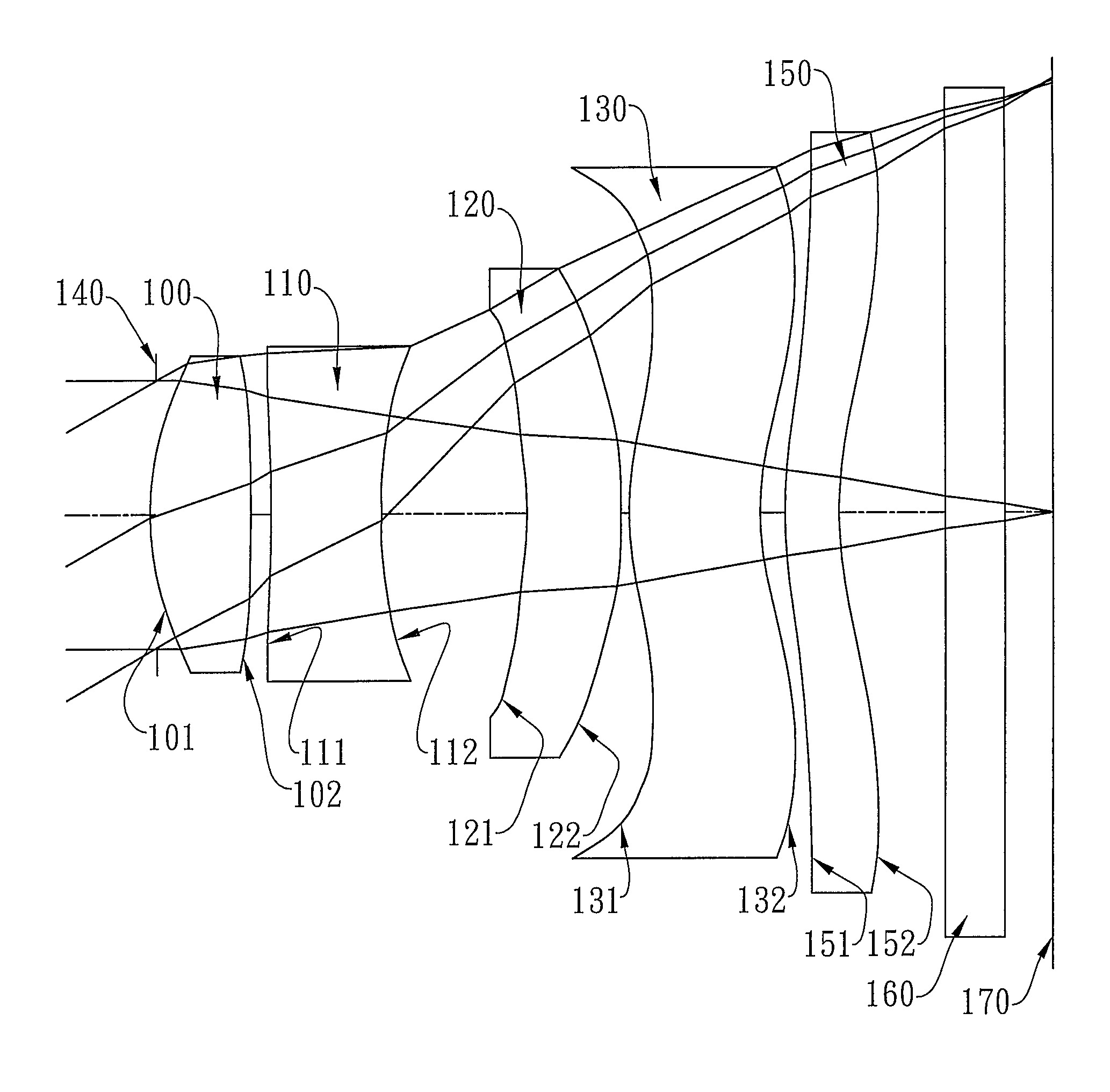
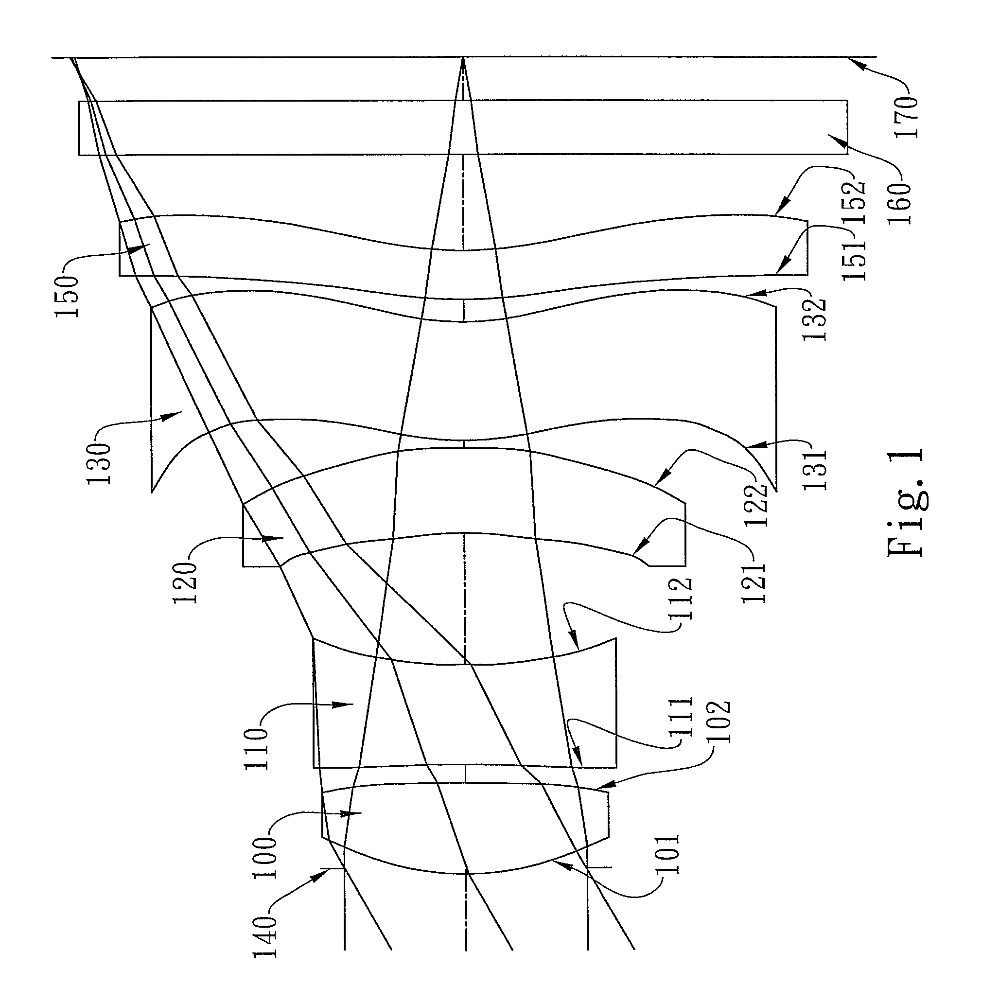
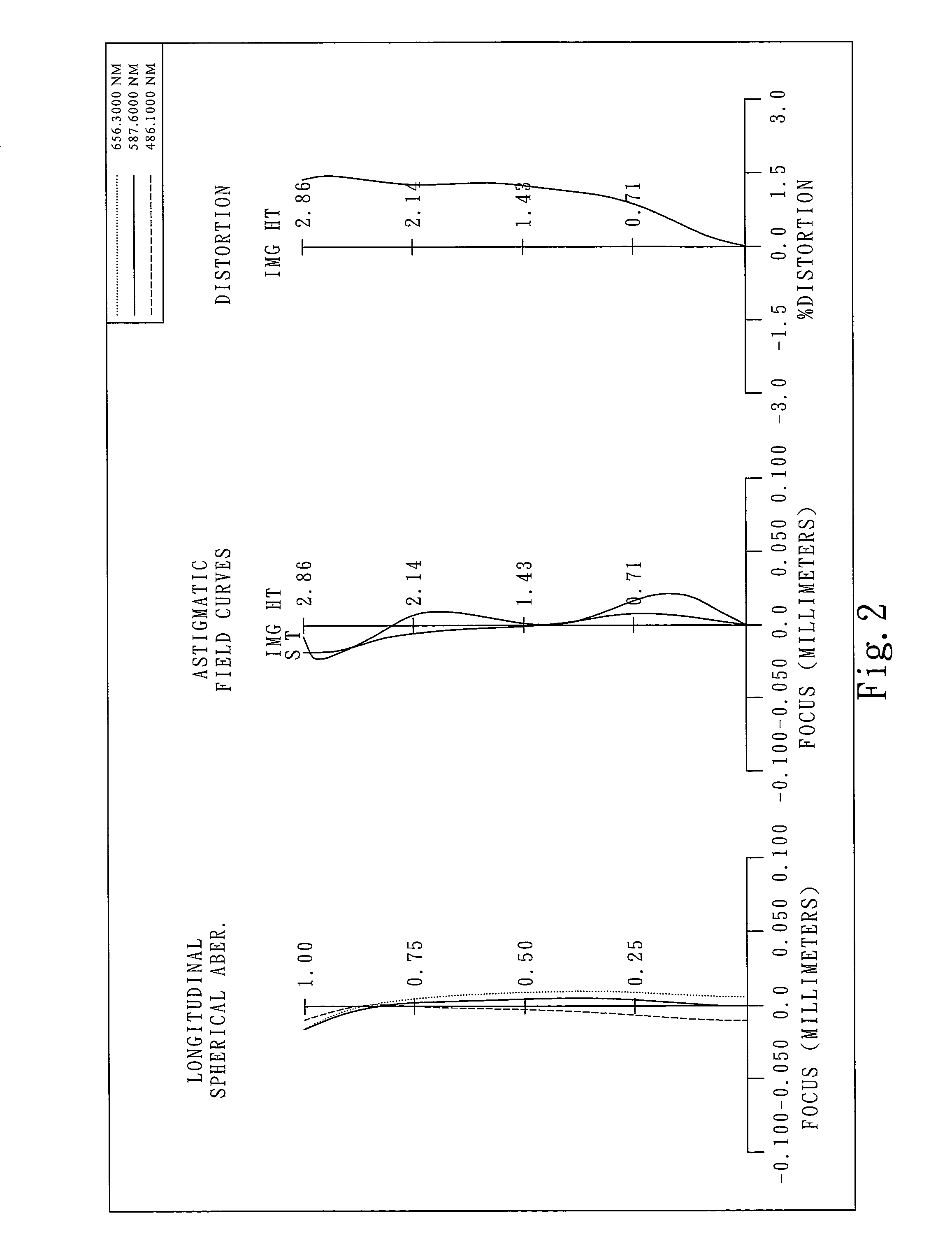
first embodiment
[0066]In the present imaging lens assembly, the focal length of the imaging lens assembly is f, and it satisfies the relation: f=4.91.
[0067]In the first embodiment of the present imaging lens assembly, the f-number of the imaging lens assembly is Fno, and it satisfies the relation: Fno=2.75.
[0068]In the first embodiment of the present imaging lens assembly, half of the field of view of the imaging lens assembly is HFOV, and it satisfies the relation: HFOV=30.0 degrees.
[0069]In the first embodiment of the present imaging lens assembly, the Abbe number of the first lens element 100 is V1, the Abbe number of the second lens element 110 is V2, and they satisfy the relation: V1−V2=32.5.
[0070]In the first embodiment of the present imaging lens assembly, the fourth lens element 130 has positive refractive power and its Abbe number Vp satisfies the relation: Vp=55.8; the fifth lens element 150 has positive refractive power and its Abbe number Vp satisfies the relation: Vp=55.9; the third le...
second embodiment
[0085]In the present imaging lens assembly, the focal length of the imaging lens assembly is f, and it satisfies the relation: f=4.19.
[0086]In the second embodiment of the present imaging lens assembly, the f-number of the imaging lens assembly is Fno, and it satisfies the relation: Fno=2.85.
[0087]In the second embodiment of the present imaging lens assembly, half of the field of view of the imaging lens assembly is HFOV, and it satisfies the relation: HFOV=34.0 degrees.
[0088]In the second embodiment of the present imaging lens assembly, the Abbe number of the first lens element 300 is V1, the Abbe number of the second lens element 310 is V2, and they satisfy the relation: V1−V2=32.5.
[0089]In the second embodiment of the present imaging lens assembly, the fourth lens element 330 has positive refractive power and its Abbe number Vp satisfies the relation: Vp=55.8; the fifth lens element 350 has positive refractive power and its Abbe number Vp satisfies the relation: Vp=55.8; the thir...
third embodiment
[0104]In the present imaging lens assembly, the focal length of the imaging lens assembly is f, and it satisfies the relation: f=4.94.
[0105]In the third embodiment of the present imaging lens assembly, the f-number of the imaging lens assembly is Fno, and it satisfies the relation: Fno=2.85.
[0106]In the third embodiment of the present imaging lens assembly, half of the field of view of the imaging lens assembly is HFOV, and it satisfies the relation: HFOV=30.1 degrees.
[0107]In the third embodiment of the present imaging lens assembly, the Abbe number of the first lens element 500 is V1, the Abbe number of the second lens element 510 is V2, and they satisfy the relation: V1−V2=32.5.
[0108]In the third embodiment of the present imaging lens assembly, the fourth lens element 530 has positive refractive power and its Abbe number Vp satisfies the relation: Vp=55.9; the third lens element 520 has negative refractive power and its Abbe number Vn satisfies the relation: Vn=30.2; the fifth le...
PUM
 Abstract
Description
Claims
Application Information