
Method and system for automated handling of errors in execution of system management flows consisting of system management tasks

a technology of system management and flow execution, applied in the field of system management flow execution, can solve the problems of complex structure, insufficient to just define, and complex flow definition (e.g. written in bpel)

Inactive Publication Date: 2011-08-16
IBM CORP
View PDF8 Cites 9 Cited by
  • Summary
  • Abstract
  • Description
  • Claims
  • Application Information

AI Technical Summary

Benefits of technology

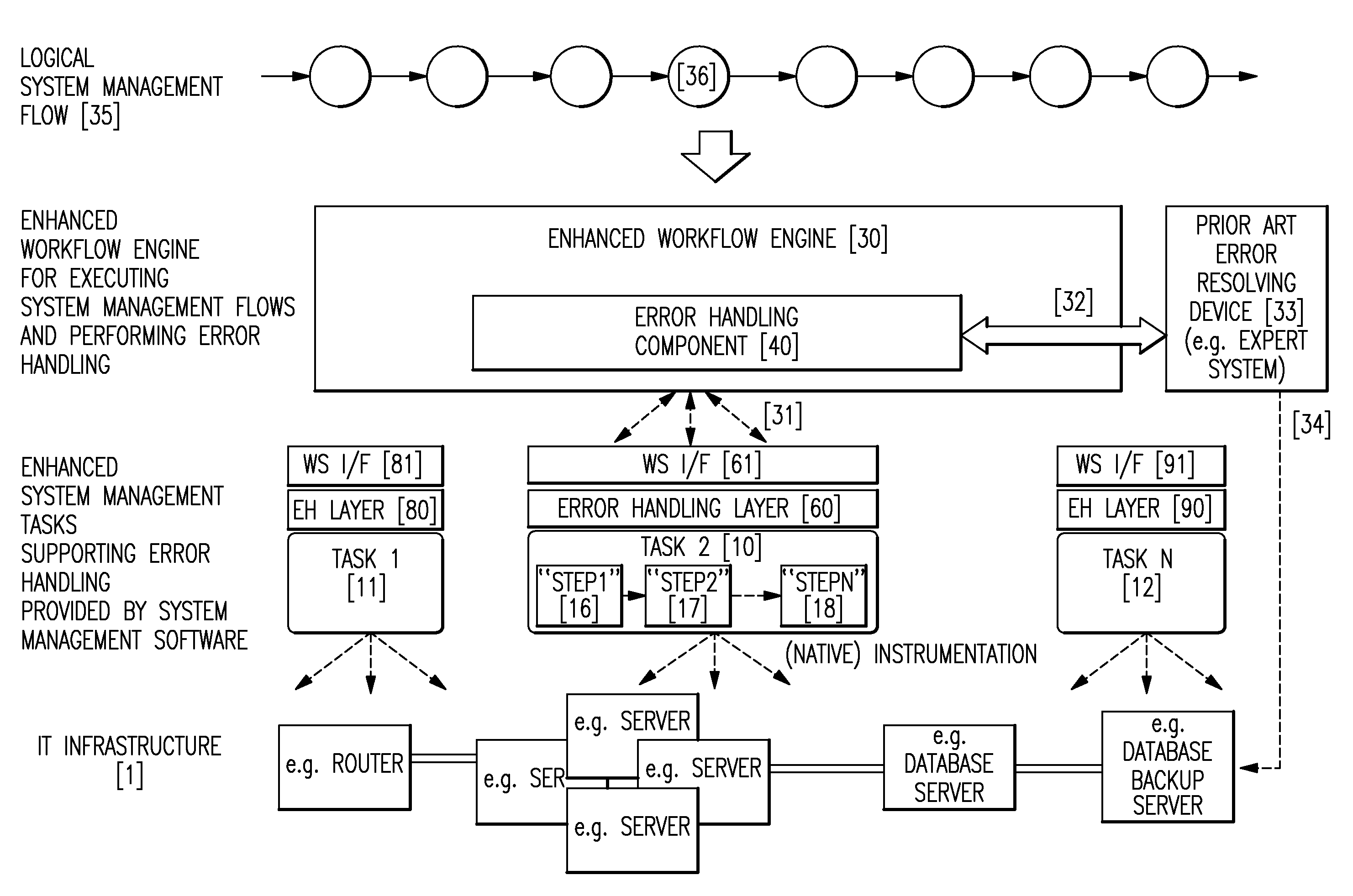
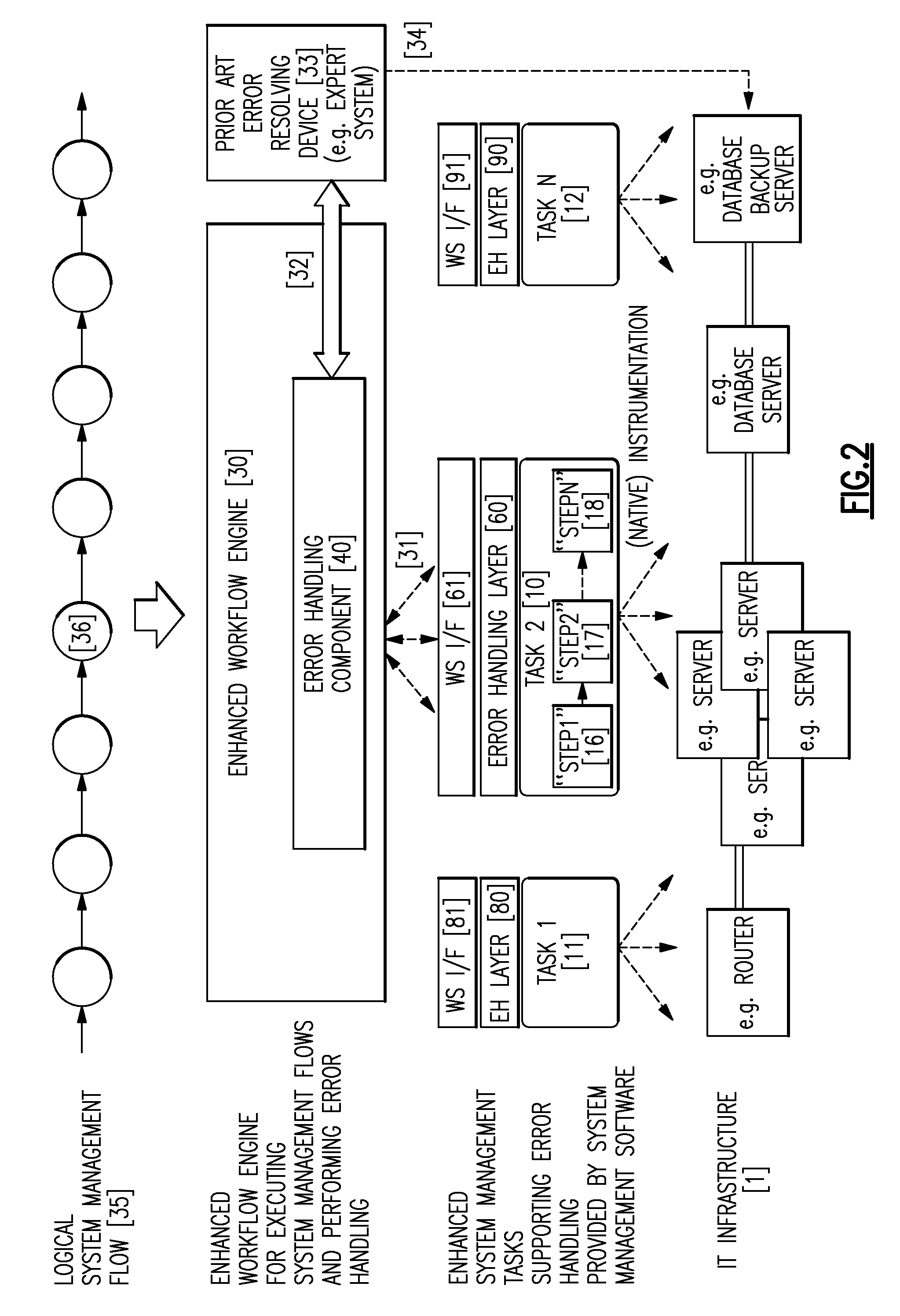
The present invention provides a method and system for automated handling of errors in execution of system management flows. This is done by enhancing workflow engines and adding a supportive error handling layer to invoked system management tasks. The additional functionality of the task-provided error handling layer is accessible for the workflow engine via extended Web services interfaces. The workflow engine error handling component and the task-provided error handling layer allow for the definition of a standard protocol between the workflow engine and invoked tasks for automated error handling. The invention simplifies error handling and allows the designer of a system management flow to concentrate on the logical structure of the flow. The system management flow just has to define the optimistic flow and the handling of errors is automatically performed by the proposed system without the need to explicitly define error handling directives in flow definitions.

Problems solved by technology

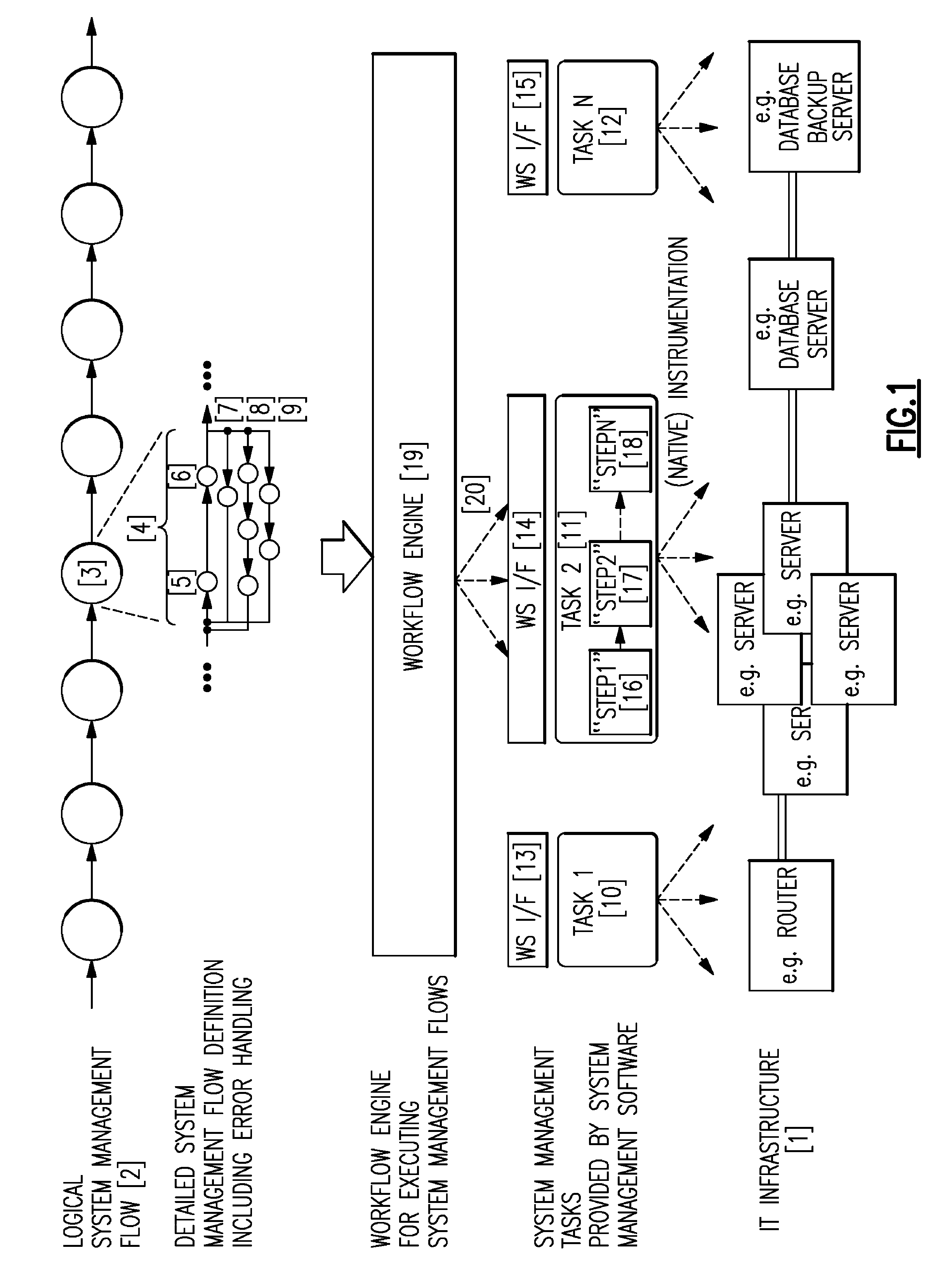
While the logical system, management flow (2) is a mostly straight-forward definition of a certain sequence of tasks, the detailed flow definition (e.g. written in BPEL) can become very complex as soon as it comes to the handling of errors that can occur in single system management tasks.
For complete error handling it is necessary to explicitly react to each potential error that can occur in sub-steps in the system management flow definition resulting in very complex constructs (4) for the invocation of one logical system management task (3).
That is, it is not sufficient to just define the logical sequence of system management task invocations, but instructions have to be included for handling each error that can potentially occur during the execution of tasks in the system management flow.
Consequently, system management flow definitions can become very complex and the designer of the flow cannot just define the simple logical structure of the flow.
On the one hand, workflow engines executing detailed flow definitions are primarily just interpreting and executing flows defined in a flow definition language (e.g. BPEL) and do not include any automatic mechanisms for handling errors.
On the other hand, there is no sophisticated communication between the workflow engine and invoked tasks other than the invoke call and the response call returned by the invoked task.
That is, there is a lack of communication (the lack of a certain protocol) concerning the handling of errors.

Method used


Image

  • Method and system for automated handling of errors in execution of system management flows consisting of system management tasks
  • Method and system for automated handling of errors in execution of system management flows consisting of system management tasks
  • Method and system for automated handling of errors in execution of system management flows consisting of system management tasks

Examples


Embodiment Construction

[0031]In the following a detailed description of the inventive error handling architecture including structure and operation of the workflow engine's error handling component (40) and of the task-provided error handling layer (60, 80, 90) as well as the interaction between both components will be described.

Error Handling Component of Workflow Engine

[0032]The processing flow of the error handling component is described in more detail with respect to FIGS. 3 and 4.

[0033]Error handling component (40) is a component within the enhanced workflow engine (30) that adds implicit error handling support to the workflow engine. This component actually adds a layer of indirection between a normal (prior art) workflow engine and the tasks invoked by the workflow engine. Each time the workflow engine invokes a task defined in the flow definition (35) in FIG. 2 this call is intercepted by error handling component (40); the workflow engine's call to invoke the task is redirected to the error handli...


PUM


Abstract

A method and system for automated error handling in system management flows by enhancing workflow engines by an error handling component and by adding a supportive error handling layer to invoked system management tasks which serves as the counterpart to the workflow engine's error handling component. The additional functionality of the task-provided error handling layer is accessible for the workflow engine via extended Web services interfaces. The workflow engine's error handling component and the task-provided error handling layer allow for the definition of a standard protocol between the workflow engine and invoked tasks for automated error handling. Furthermore, an interface and method of communication between the enhanced workflow engine and an external error resolving device (such as an expert system) is defined with the purpose of using the external error resolving device for automatic error recovery. The internal or external error resolving device is capable of performing corrective actions on the managed IT infrastructure using mechanisms outside the scope of this invention. The benefit of the presented architecture is that the complexity concerning error handling is completely removed from system management flow definitions, and the designer of a system management flow can concentrate on the logical structure of the flow (e.g. the correct sequence of tasks).

Description

CROSS-REFERENCE TO RELATED APPLICATION[0001]This application claims the priority benefit under 35 U.S.C. §119 of European application 06121216.3, filed Sep. 25, 2006, and incorporated herein by reference.BACKGROUND OF THE INVENTION[0002]1. Field of the Invention[0003]The present invention relates to executions of system management flows, and in particular to a method and system for automated handling of errors in execution of system management flows consisting of system management tasks.[0004]2. Description of the Related Art[0005]The present invention is concerned with the management of complex IT infrastructures (1) consisting of distributed heterogeneous resources (see FIG. 1). The management of such IT infrastructures is—in most cases—done by performing a number of system management tasks (tasks) in a certain sequence an order to reach a certain management goal. Such a sequence of system management tasks is called a system management flow (2) within this invention.[0006]Each tas...

Claims


Application Information

Patent Timeline
Patent Type & Authority Patents(United States)
IPC IPC(8): G06F11/00G06F9/46
CPCG06Q10/06311G06Q10/0633
Inventor BREITER, GERDMAAS, RUEDIGERROST, STEFFENSPATZIER, THOMAS
Owner IBM CORP
Learn More