Pad for helmet or the like

a technology for helmets and pads, applied in the field of pads, can solve the problems of premature deterioration, not only requiring a tedious and expensive manufacturing process, and rendering the pads useless for their intended purpos

Inactive Publication Date: 2011-08-23
REMINGTON PROD INC
View PDF23 Cites 26 Cited by
  • Summary
  • Abstract
  • Description
  • Claims
  • Application Information

AI Technical Summary

Benefits of technology

[0006]It is thus an object of one aspect of the present invention to provide a protective pad which is manufactured without the need of an encapsuling bag.
[0007]It is an object of another aspect of the present invention to provide a protective pad, as above, which is simple and inexpensive to manufacture.
[0008]It is an object of an additional aspect of the present invention to provide a protective pad, as above, which is constructed of materials designed to absorb forces while providing comfort to the user.
[0009]It is an object of yet another aspect of the present invention to provide a protective pad, as above, which is not subject to premature deteriorization.

Problems solved by technology

These pads not only require a tedious and expensive manufacturing process, but also are subject to premature deteriorization.
In particular, with frequent removals and replacements, the integrity of the plastic bag can be invaded thereby rendering the pad useless for its intended purpose.

Method used


Image

  • Pad for helmet or the like
  • Pad for helmet or the like
  • Pad for helmet or the like

Examples


examples

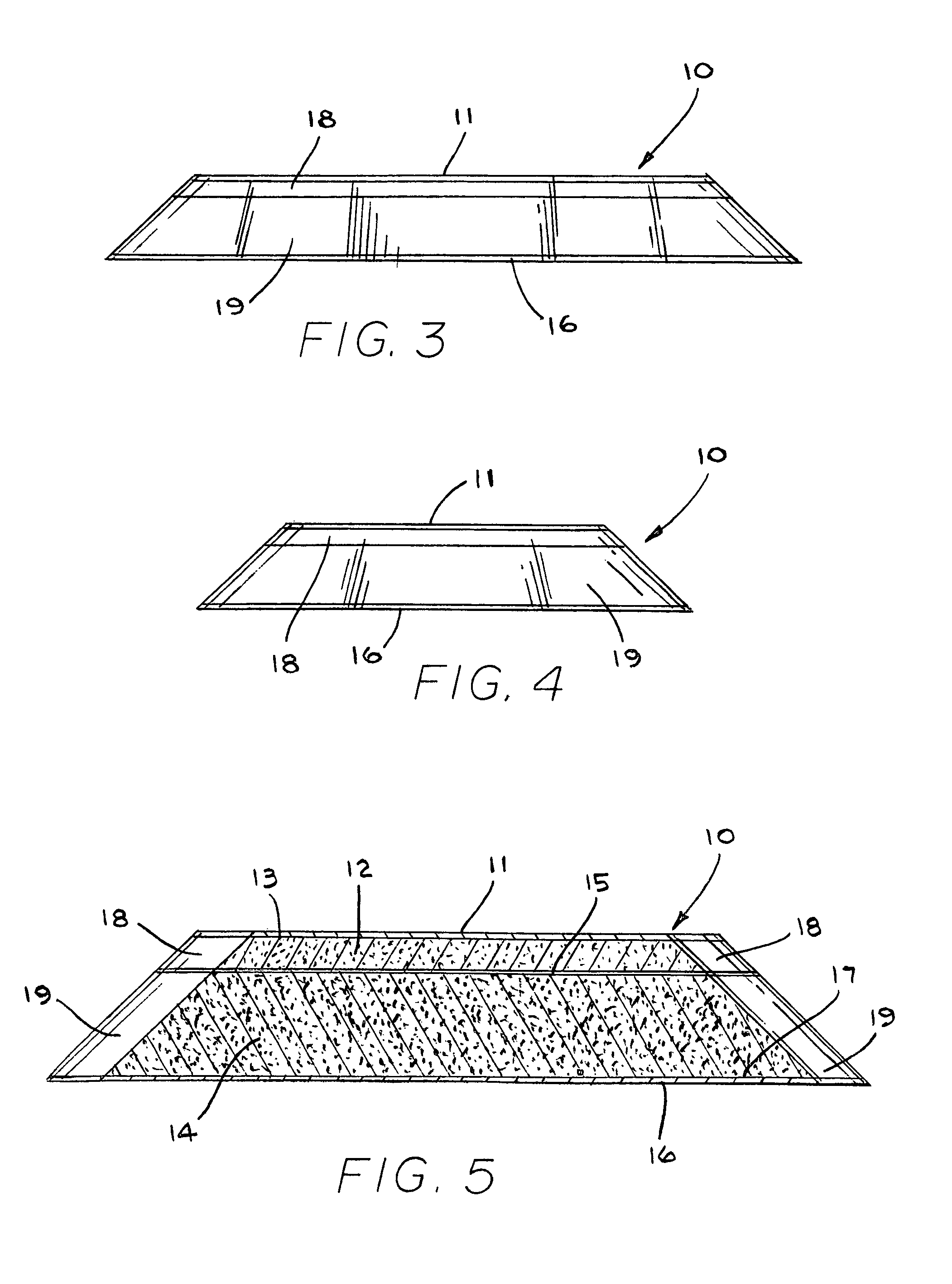
[0038]Example 1 was a 1 inch thick sample of a rate dependent, moisture-resistant foam. Specifically, Example 1 was formed by combining two layers of PORON® XRD™ 12500 foam. Example 2 was a combination of a 0.5 inch thick viscoelastic foam layer, a 0.25 inch thick rate dependent, moisture-resistant foam layer, and a 0.125 inch thick non-rate dependent polyurethane foam layer. Accelerometer Impact Data was measured as follows:

Drop weight 11 lbs.

Drop height 0.48 meters

Drop velocity 3.03 meters / second

Drop timing 3 material impacts with 60-75 seconds between impacts

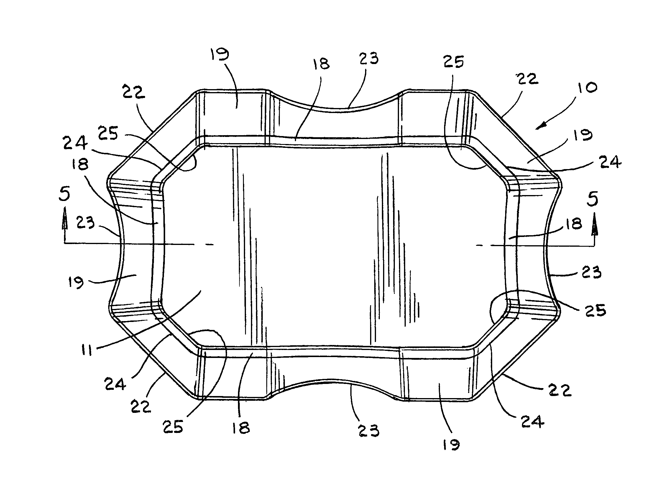
Sample dimensional size 5 inches by 7 inches

[0039]Results are summarized in Table 2.

[0040]

TABLE 2EXAMPLE 1EXAMPLE 2HIT #1 (g)5369HIT #2 (g)5178HIT #3 (g)5082AVERAGE (g) 5276

[0041]It can be seen that acceleration remains fairly constant from hit #1 to hit #3 for Example 1, while degradation is observed for Example 2. The degradation in Example 2 is believed to be due to the slower recovery from compression of the viscoelastic ...


PUM


Abstract

A pad (10), a plurality of which can be positioned in a helmet (21) or the like for comfort and protection, includes a first generally rectangular fabric material (11) having truncated corners (25). A first generally rectangular foam material (12) having truncated corners (24) includes a top surface, a bottom surface, and side surfaces (18), the top surface being attached to the first fabric material (11). A second generally rectangular foam material (14) having truncated corners (22) includes a top surface, a bottom surface, and side surfaces (19) having a scallop (23), the top surface being attached to the bottom surface of the first foam material (14). A second generally rectangular fabric material (16) having truncated corners (22) and sides having a scallop (23) is attached to the bottom surface of the second foam material (14). The side surfaces (18, 19) of the first and second foam materials (12, 14) are exposed. The first foam material (12) is an open-celled polyurethane, and the second foam material (14) is an impact rate dependent polyurethane having a thickness at least as great or greater than the thickness of the first foam material (12).

Description

TECHNICAL FIELD[0001]This invention relates to a pad used for protection. More particularly, this invention relates to such a pad, a plurality of which may be positioned in a helmet or the like to provide comfortable protection.BACKGROUND ART[0002]People are involved in a number of endeavors which require that their bodies be protected. Many athletic participants, for example, are required to wear helmets, which helmets are provided with padding for protection of their heads. Similarly, other body parts may be in the need of padding during athletic events, such as the chest protectors of baseball catchers or umpires.[0003]Military helmets, in particular, provide a special need for padded helmets. There, usually the inside of a helmet is provided with a plurality of pads which may be selectively positioned in the helmet dependent on the desire of the soldier. In addition, individual of the pads may be replaced, as needed or desired, when they become worn or otherwise damaged by moist...

Claims


Application Information

Patent Timeline
Patent Type & Authority Patents(United States)
IPC IPC(8): A41D27/28A41B3/12A41D27/12A41D13/05
CPCA42B3/127
Inventor CULLEY, BRIAN J.SMICKLEVICH, MICKEY
Owner REMINGTON PROD INC
Why Eureka
Try Eureka