Adjustable and foldable V-shaped hay rake

a hay rake, adjustable technology, applied in the field of agricultural tools, can solve the problems of not being entirely satisfactory from all points of view, being more complex and expensive than other hay rakes, and not being able to meet the needs of use, and achieve the effects of convenient operation, low construction cost, and high efficiency

Active Publication Date: 2011-08-23
SITREX
View PDF14 Cites 11 Cited by
  • Summary
  • Abstract
  • Description
  • Claims
  • Application Information

AI Technical Summary

Benefits of technology

[0004]These problems and inconveniences may be addressed by the hay rake described herein, which, because of its innovative design, not only is highly effective in its hay gathering capacity, but is also more robust, simpler, and thus less expensive to build and easier to operate.
[0006]The arm may be arranged such that any adjustments to the wing orientation may be effected at the arm without the need for additional components such as, e.g., support members that attach to the wing and to the arm and / or central frame to set the wing angle. For example, according to some examples of the present invention, the angle of the wing with respect to the arm and / or central frame and the distance of the wing from the central frame may be altered solely by making adjustments on the arm, such as, e.g., moving a pin between different holes in the arm. In this manner, the distance of the wing from the central frame may be altered by telescoping the arm and setting the arm length with a pin that is inserted through holes in each of the telescoping sections of the arm, and the angle of the wing may be adjusted by rotating the wing and fixing the rotational position by inserting a single pin through both a hole in the arm and a hole in the wing. Further, as the rotation of the wing assembly between the upward position and the outward position may occur at a single joint at the end of the arm opposite the wing, all movement and adjustments of the wing with respect to the central frame may occur via a single arm, thus providing a highly flexible system with a relatively small number of parts. This relatively low level of complexity may allow for lower manufacturing costs and less potential points of failure from a reliability standpoint.

Problems solved by technology

None of the hay rakes available so far, however, is entirely satisfactory from all points of view.
While they all may be successful with respect to accomplishing the hay gathering task for which they were designed, they also may be more complex and expensive than is desirable given the great need for these important agricultural tools.

Method used


Image

  • Adjustable and foldable V-shaped hay rake
  • Adjustable and foldable V-shaped hay rake
  • Adjustable and foldable V-shaped hay rake

Examples


Embodiment Construction

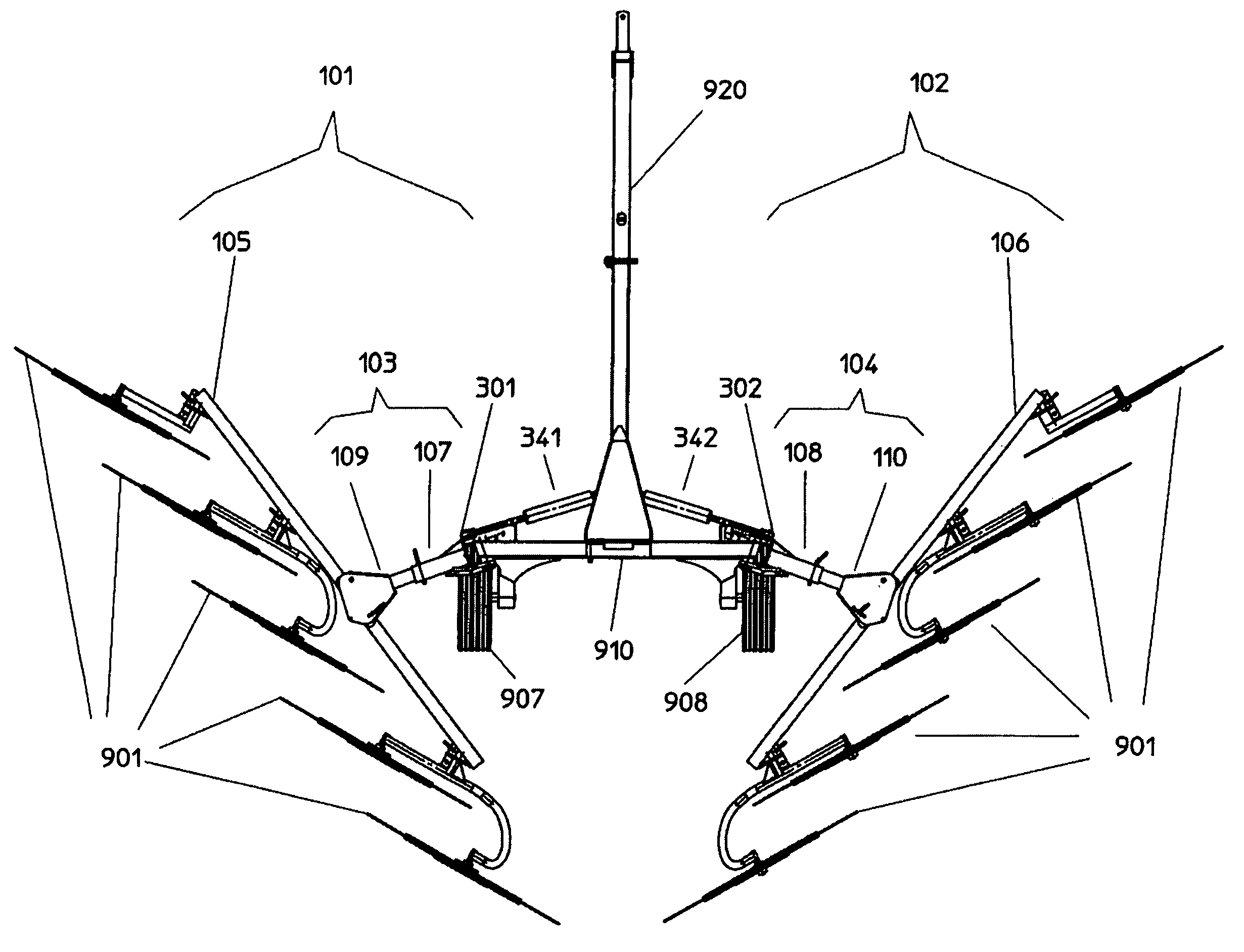
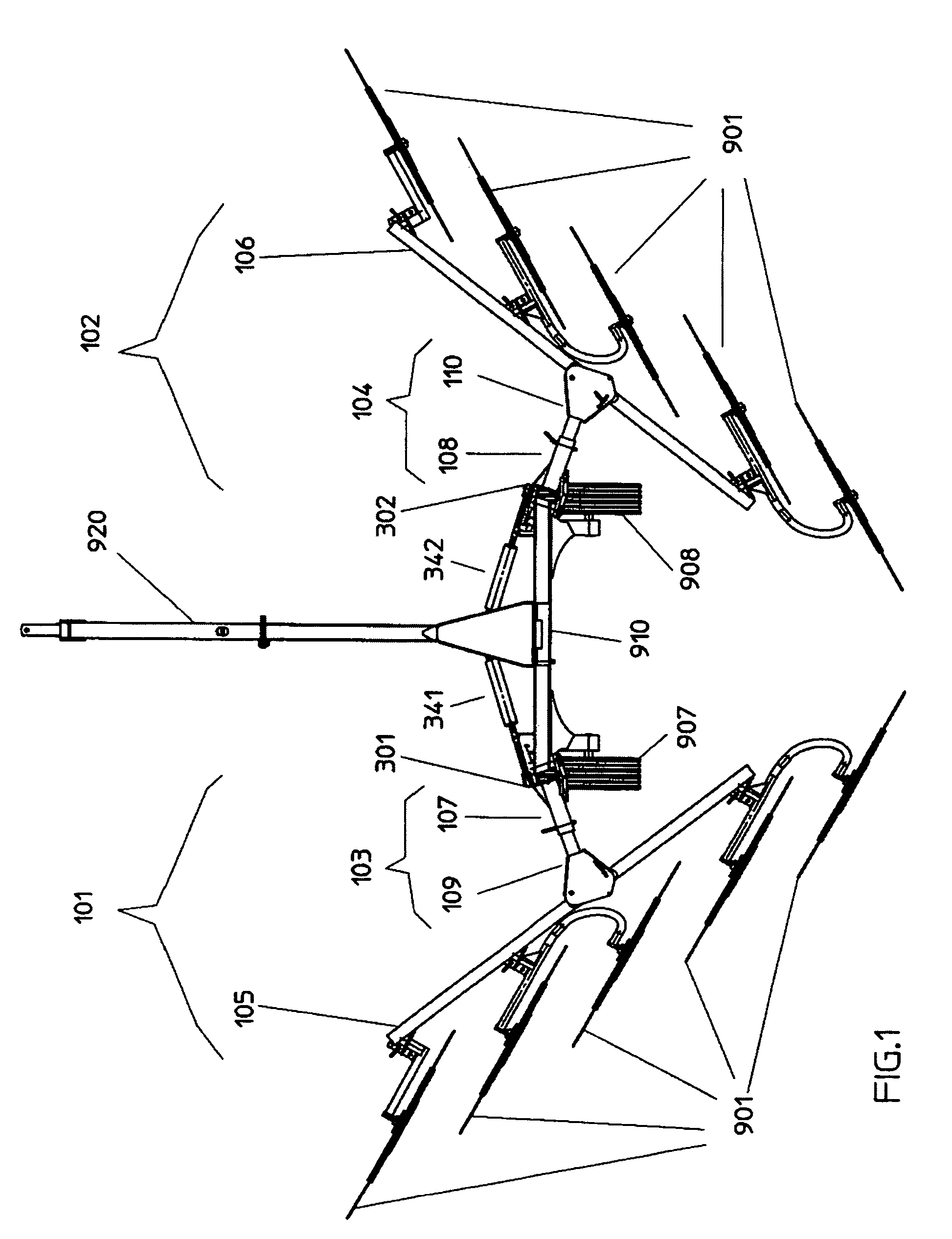
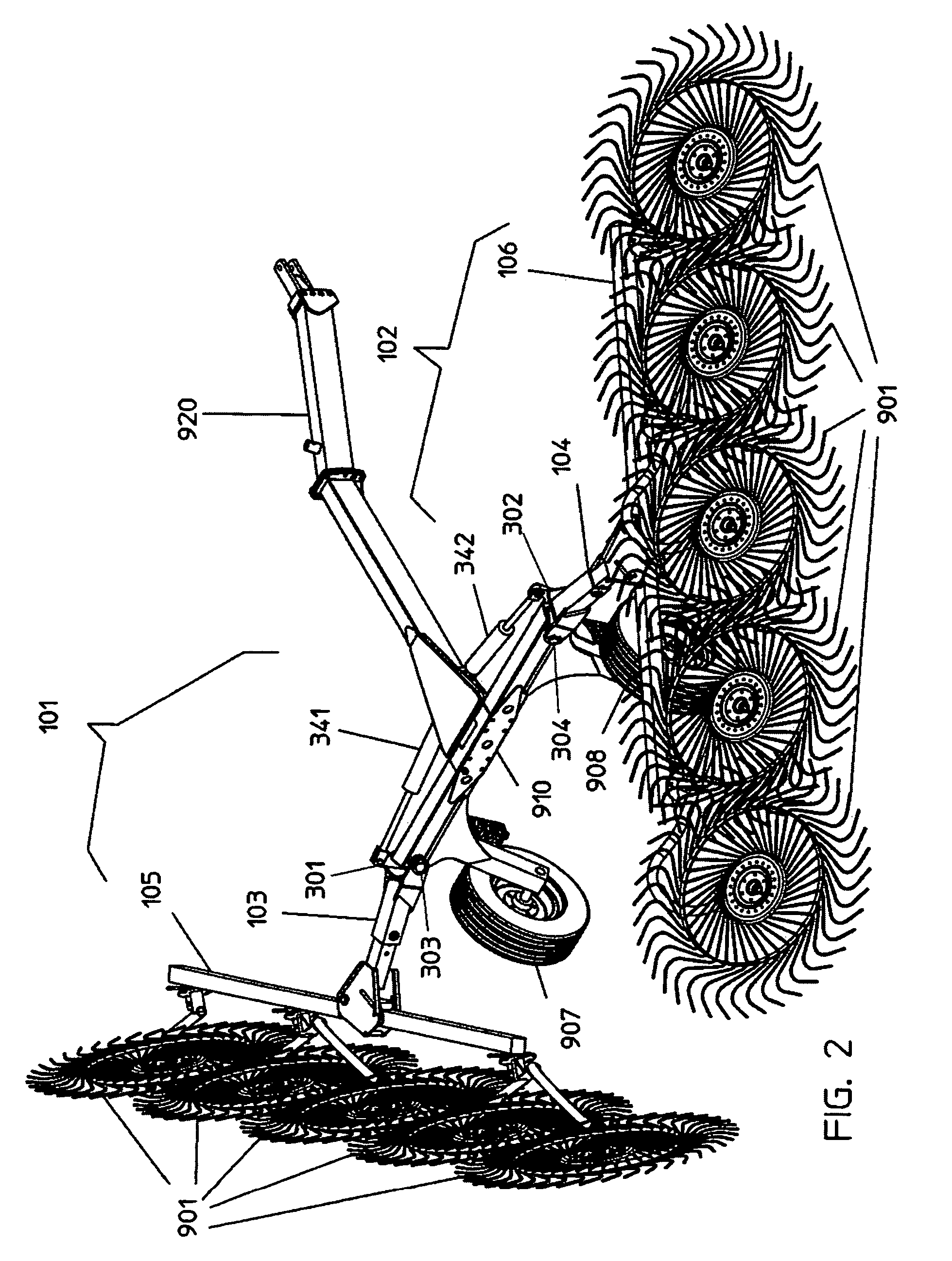
[0038]For ease of reference the same reference numbers are used to designate the same or corresponding elements throughout the Figures. Referring to FIGS. 1 to 5c, one exemplary embodiment of the rake of the invention includes a central frame 910, which includes a transverse member 911, equipped with a tow bar 920 that extends in a frontward direction and roller wheels 907 and 908.

[0039]A “T”-shaped adjustable hay rake arm or wing assembly 101, 102 is rotatably connected to either end of the transverse member 911. The “T”-shaped adjustable rake arms 101, 102 are composed of extendible arm sections 103 and 104 and mobile wings or wing sections 105 and 106. Each of the extendible sections 103 and 104 of the respective rake 20 arms 101 and 102, is composed of a first longitudinal section 107, 108 and a second longitudinal section 109, 110. The first and second longitudinal sections are configured so that they slide telescopically with respect to one another. Each of the first longitudi...


PUM


Abstract

An adjustable and foldable V-shaped hay rake is an agricultural tool used for raking hay on fields, in which, for each arm of the hay rake, all the mechanisms for moving the arm are centered on a single adjustable master support plate.

Description

FIELD OF THE INVENTION[0001]The present invention concerns an agricultural tool used for gathering hay. More particularly, it relates to a towable adjustable and foldable V-shaped hay rake.BACKGROUND INFORMATION[0002]Towable hay rakes having two adjustable rake arms provided with hay raking wheels, in which the rake arms are movable, usually by the action of one or more hydraulic cylinders, from a folded transport position to a working “V” position for gathering hay in the field are known. Such towable hay rakes include, for example, those described in U.S. Pat. Nos. 4,183,198, 4,214,428, 4,753,063, 4,974,407, 4,977,734, 6,405,517 and 7,318,312.[0003]None of the hay rakes available so far, however, is entirely satisfactory from all points of view. While they all may be successful with respect to accomplishing the hay gathering task for which they were designed, they also may be more complex and expensive than is desirable given the great need for these important agricultural tools.S...

Claims


Application Information

Patent Timeline
Patent Type & Authority Patents(United States)
IPC IPC(8): A01D80/00
CPCA01D78/144
Inventor MENICHETTI, SILVANOPETTURITI, SAURO
Owner SITREX
Why Eureka
Try Eureka